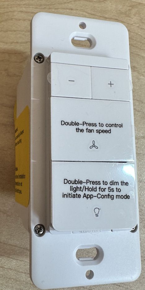
I recently purchased a couple of Treatlife DS03 Smart Dimmer / Fan controller.
Naturally, I had no desires to use the Tuya cloud services and wanted to connect it directly to my Home Assistant setup.
There were many guides that one could find, but none of them was complete (using phrases like "do it in the usual way"). As someone new to both HA and OpenBeken world, I've had some trouble getting a definitive answer on how to get the process across. To make matters worse, I only have a Mac machine so all the windows flashing guides weren't very usable for me
After some trial and error and time spent on research, I've decided to put down the following guide for prosperity. Hope someone finds in useful in the future.
 1. Disassemble the board
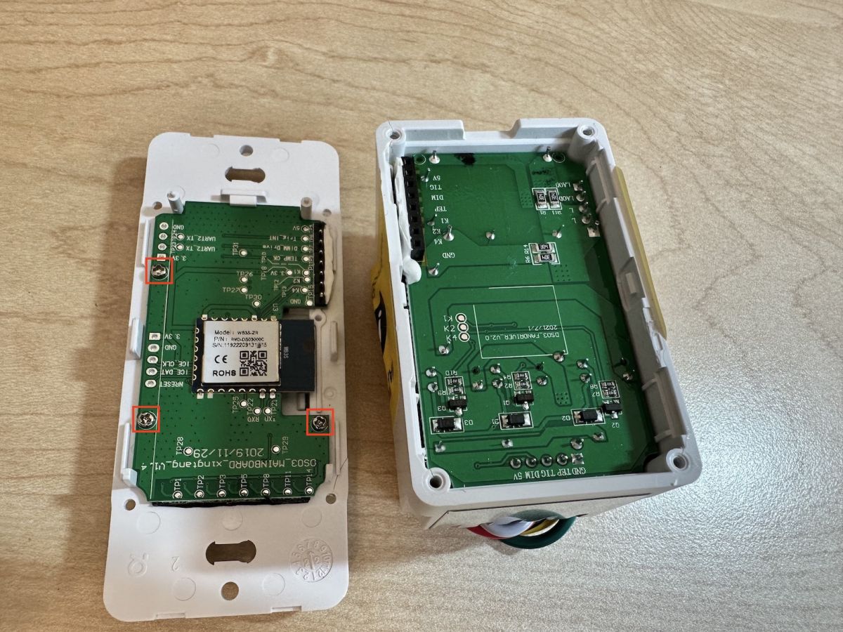
Open the four screws connecting the face plate and carefully pry open the panel (which contains the WB3S board)
 2. (Optional) Remove board with WB3S board from buttons
Remove 3 small screws and disconnect main board from panel (marked above in red)
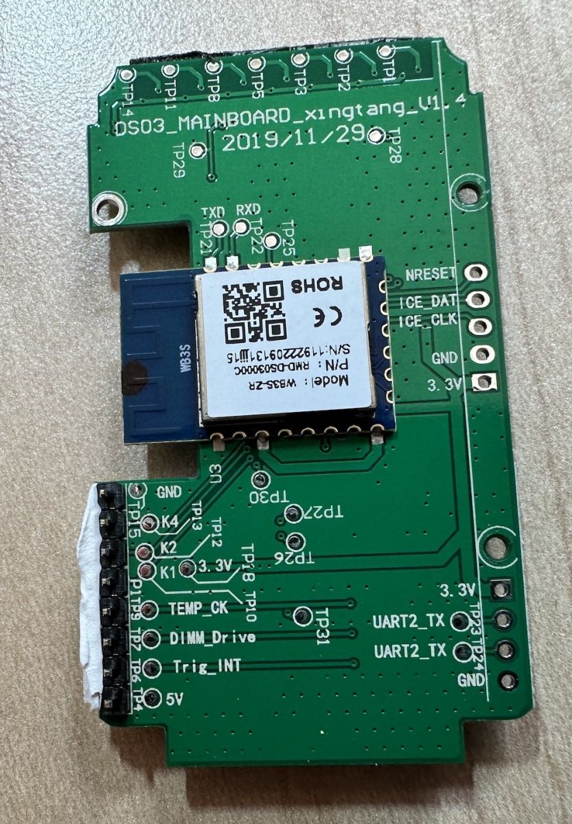
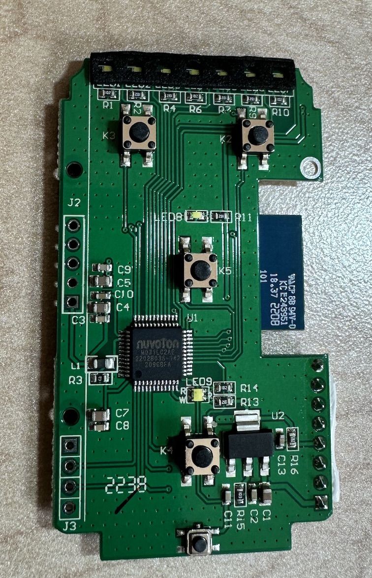
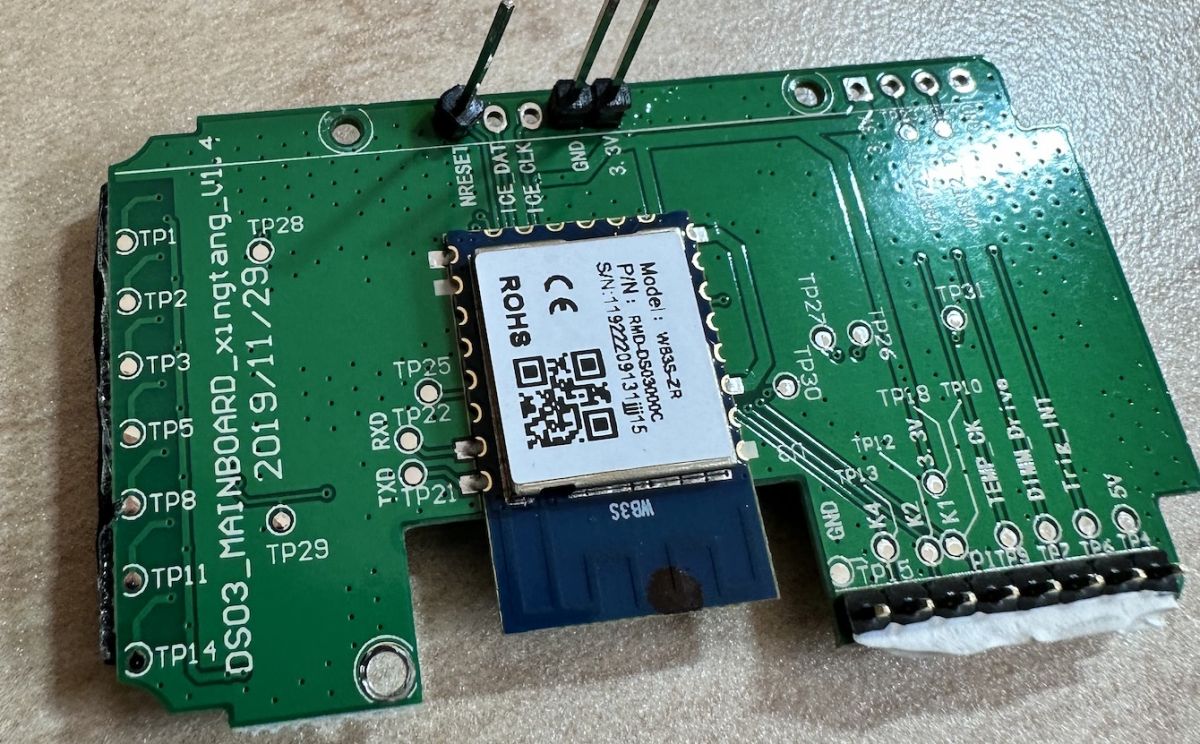
You should end up with the following board (both sides shown below)


3.
Soldering wiring and pins
In order to flash OpenBeken on this chip we're going to need to use the UART interface of the WB3S board. However this interface is already used by the Tuya software to communicate with the Tuya MCU (Novton board on opposite side) that's actually controlling the leds and GPIOs.
So we need to expose the UART wires and reset the MCU so that we can chat without interruption
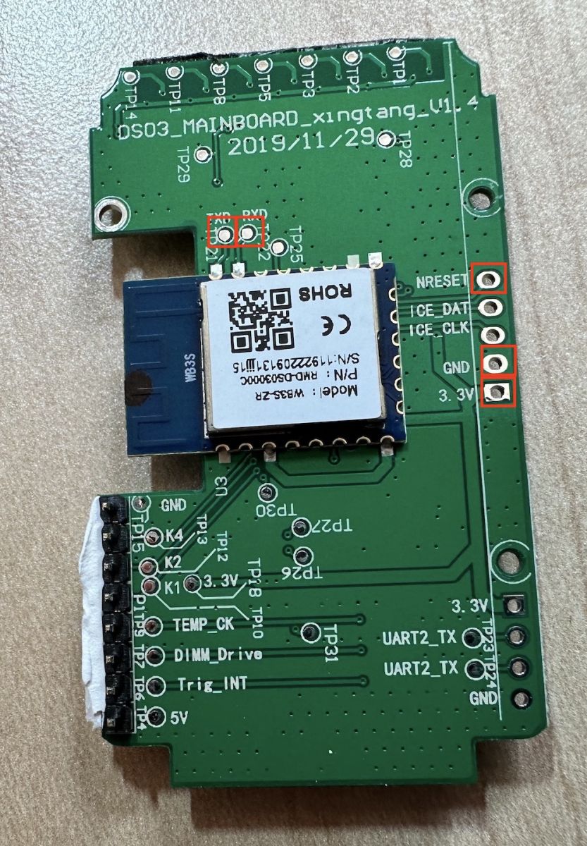
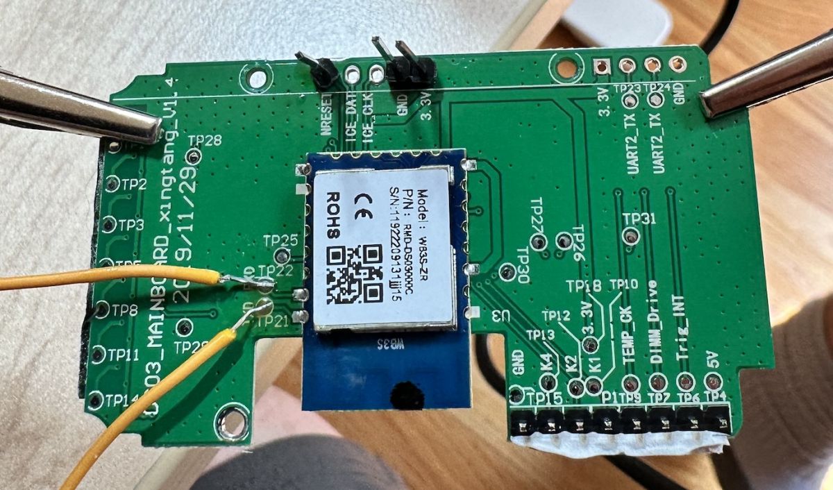
Solder pins / wires on the 3.3V, GND, nRESET, TX & RX lines, marked below
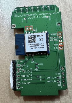
Solder the pins
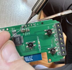
Solder the wires
If you're not experienced in soldering, verify all the connectivity with a multimeter.
4. Connect to USB-to-TTL board
I'm using
this board and use the following connections. Notice that RX on the board is TX on the USB-to-TTL and vice versa.
| DS03 Mainboard | USB-to-TTL |
| 3.3v | vcc |
| GND | GND & NRESET |
| TXD | RXD |
| RXD | TXD |
Note, in order to connect the USB-to-TTL GND to both GND and NRESET, I used a small breakout board as seen below
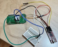
And connect the USB-to-TTL to your computer (my MBP in my case)
5. Install python and install the bk7231tools package so we can flash the firmware
We're going to install the
bk7231tools package to support flashing
6. Check connectivity and see if we're able to communicate with the board
7. What happens if the above fails (usually timeout)
In some of the boards the above worked without issue, while in another board I could not get the above to work at all. The problem seems to have been that the Tuya app was trying to talk over the UART with the MCU (which is held at reset) and would only give a small time window at boot time to talk with the bootloader.
The solution comes from reseting the board while the python script was already running (the
bk7231tools script is internally flooding the serial).
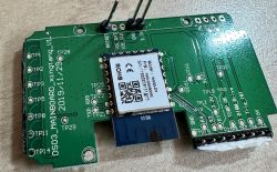
Reseting is done by shorting the CEN pin on the WB3S board to GND.
However the USB-to-TTL board I've had didn't appreciate the" "short" here and reseted themselves (disconnecting the USB).
The below describes what one can do if that happens:
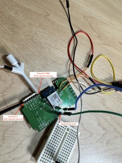
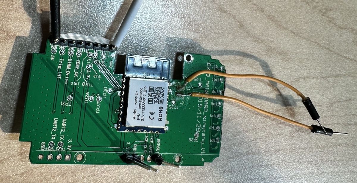
7.1 Use a
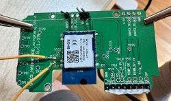
separate 5V power source and connect it to the 5v connectors as marked below. Disconnect the 3.3V source from your USB-to-TTL converter. In my case I used another USB-to-TTL with the jumper set to 5V.
Do not use TX/RX on this device as it may damage the WB3S.
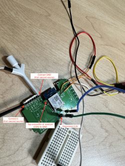
7.2 Run the bk7231tools command as above and while it waits, tap connect the GND to the CEN pin as marked below (to reset the WB3S) board. See below on locations. I connected another connection to the breakout board connected to GND and used the other side of the wire to momentarily tap the wire on the CEN pin, quickly reseting the board.
7.3 The python script should work now as expected
8. (Optional) Create a backup of your existing firmware
9. Write new firmware on the device
Download the relevant OpenBeken image from
OpenBK7231T github page. Use the UA version (UART firmware). At the time of this writing the the file I used was OpenBK7231T_UA_1.17.147.bin
Use the following commands to write (notice we're using the offset of 0x11000 which is after the bootloader)
Success! Our WB3S is now using OpenBeken!
10. Disconnect all but the 5V power and 5V GND

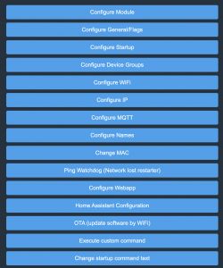
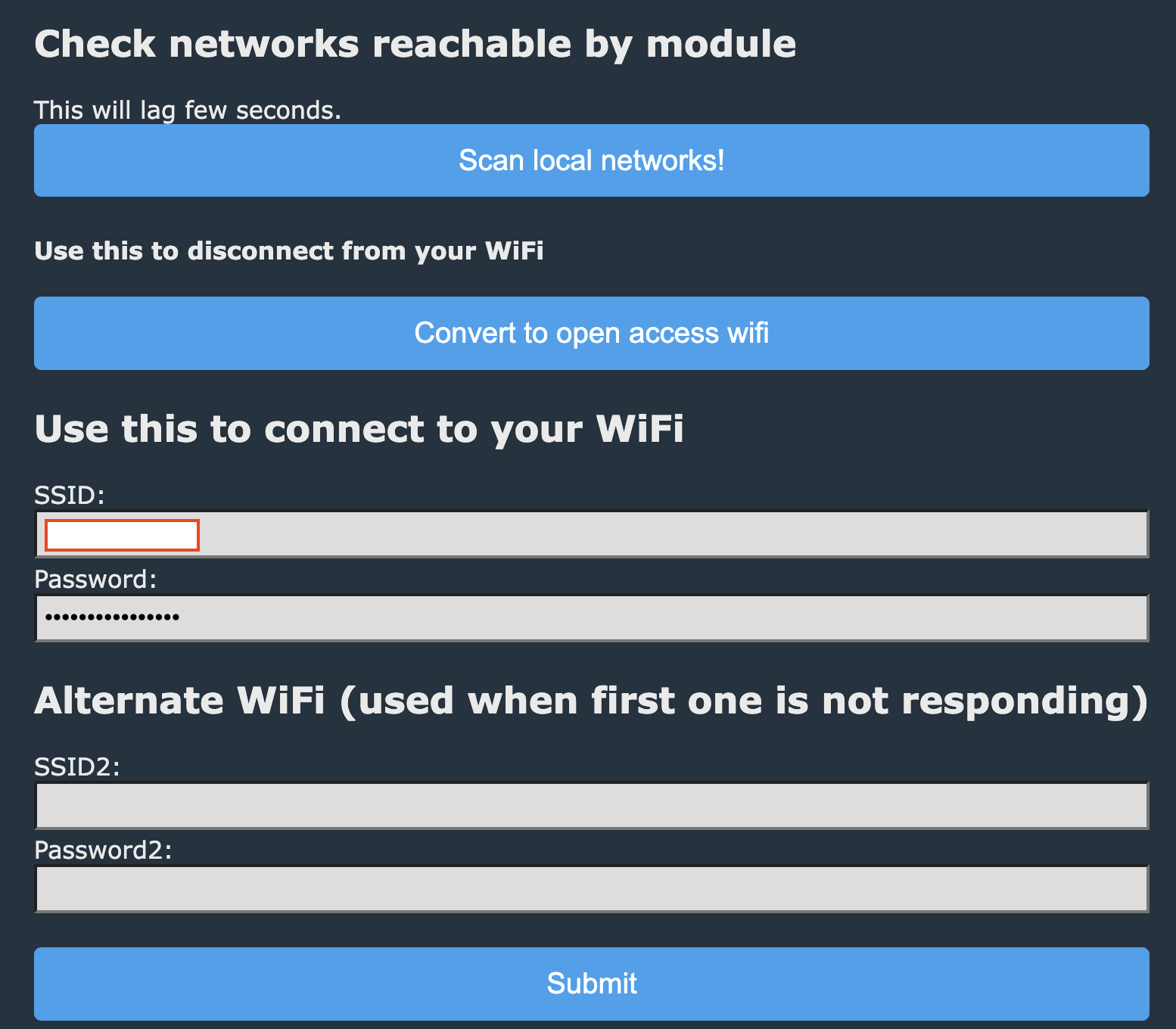
[b]11. Configure the OpenBeken software to connect to your wifi
Connect your computer to the OpenBeken SSID and browse to 192.168.4.1
Configure the wifi details
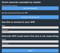
Restart the WB3S and connect to it's IP address (use your router's interface to find it)
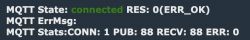
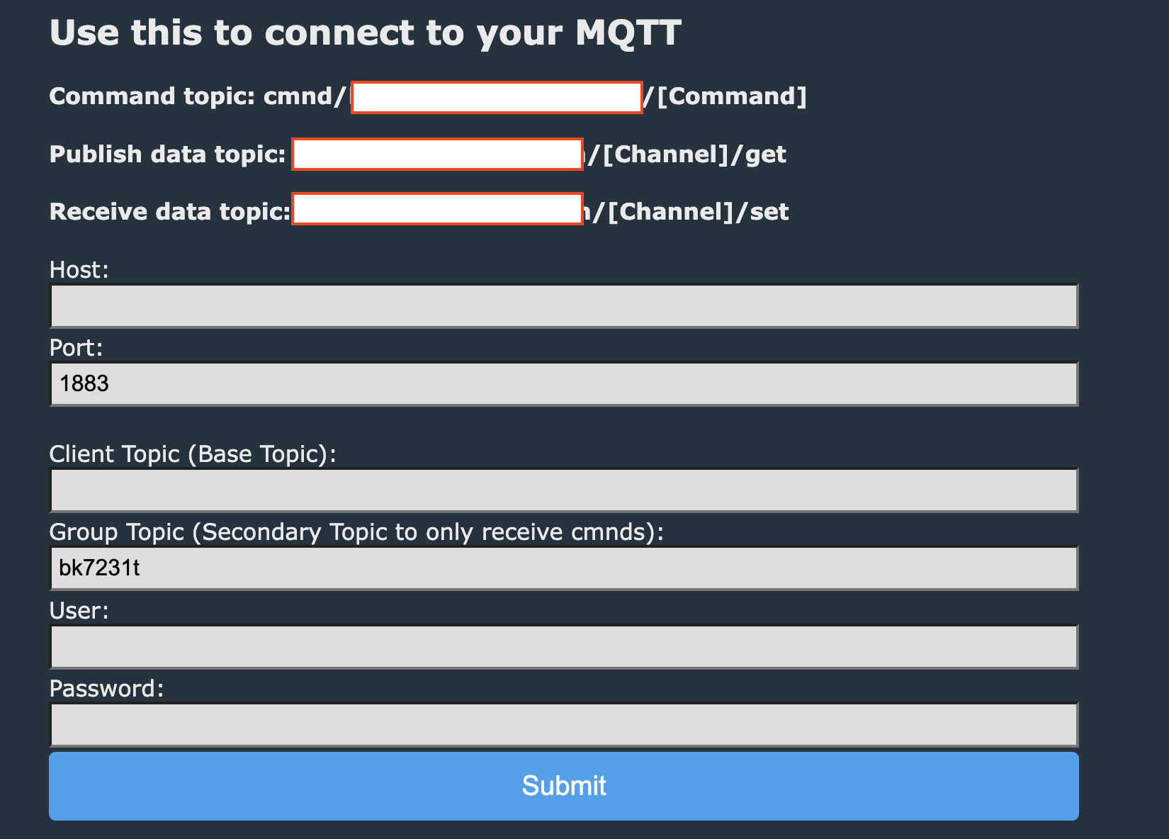
12. Configure names and MQTT parameters

And it should connect to MQTT in your setup
 13. Write an autoexec.bat file
Click Launch Web Application and click on Filesystem
Create a file called
autoexec.bat and set it's content to
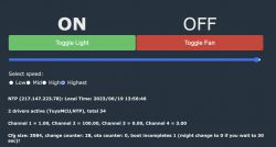
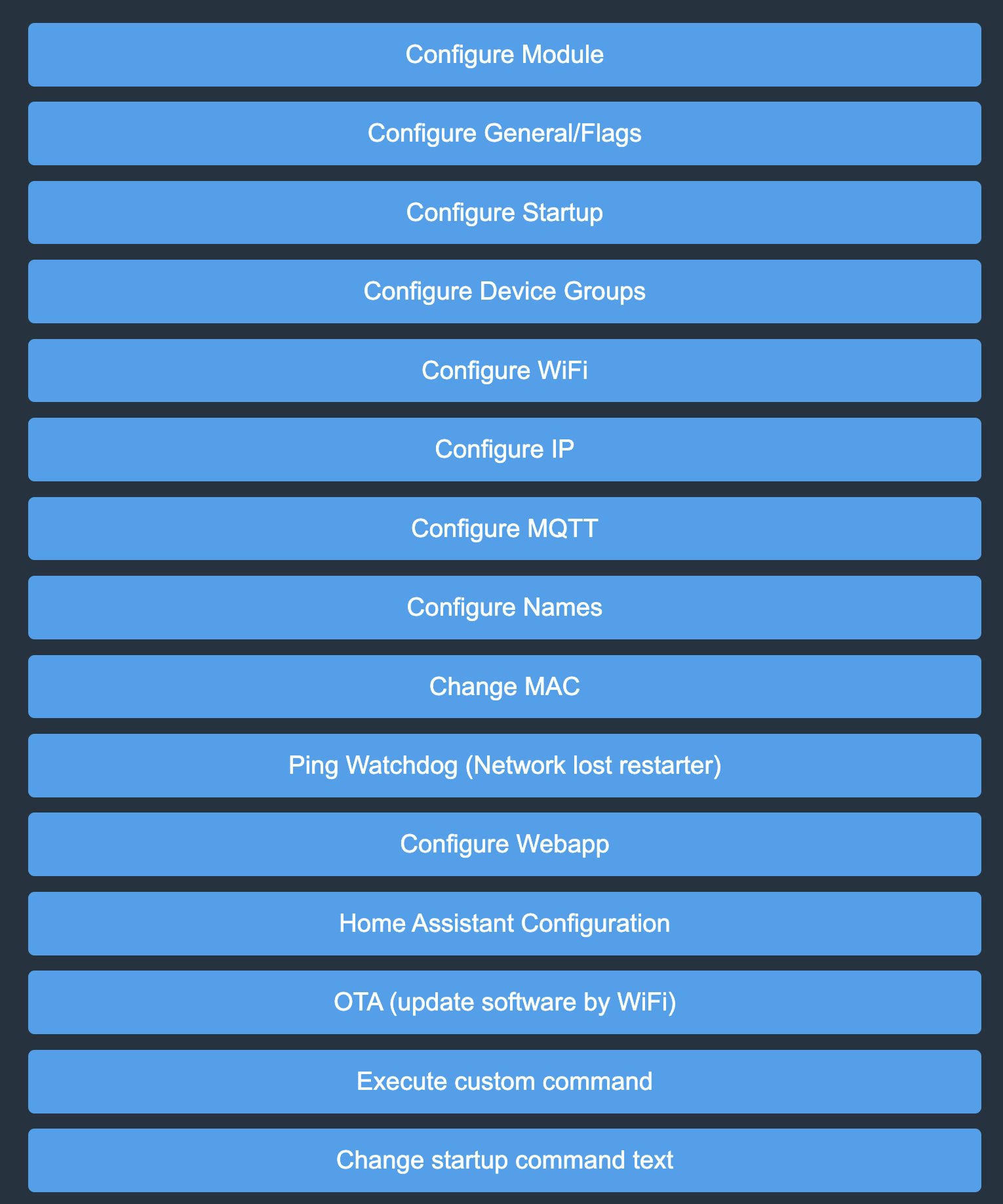
Reboot
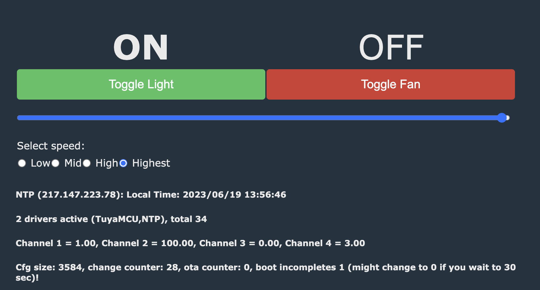
The firmware should now look like this
 14. Connect to Home Assistant.
You can either create an MQTT discovery through OpenBeken (Config->Home Assistant Configuartion) or use the following in HA
15. Unsolder the wires and pins from the board
And put everything back together
Congrats.[/b]


Comments
Very good and detailed guide. Here are few more tips from me: - you can use SSDP driver to get your device discoverable by Windows (startDriver SSDP in autoexec.bat) - you can use power save to lessen... [Read more]
Awesome. Thanks! [Read more]
I found that the OpenBeken heuristics for Home Assistant discovery isn't great for this device. It creates the fan switch as a light switch, ignores the fan speed setting. I wasn't happy with it. The... [Read more]
Very good job. I am planning to customization option for OBK hass automatic discovery, maybe that could also help in the future. It will be most likely possible through our Web App. [Read more]
Just as an FYI for any one else looking into these. I bought both a single and the 2 pack off of amazon. The single pack had the BK7231T chip, but the 2 pack had the BK7231N chip. Not sure how different... [Read more]
Do you have flash backups for both N and T versions? Can you submit them here? [Read more]
Yes I do! Hopefully they attached correctly. [Read more]
I just experienced this too. There are three boards inside on top of each other and they're all soldered together. I removed the two screws on the metal faceplate and wiggled the assembly out. In order... [Read more]
28 pin DIP MCU, are you sure? That would be a very large case, as for Tuya device... https://obrazki.elektroda.pl/5771956700_1728281264_thumb.jpg [Read more]
Well not technically a dip but rectangular with pins on 2 sides https://obrazki.elektroda.pl/1698324000_1728296627_thumb.jpg Note how the 5th pin on the top has no trace, that’s the reset pin. ... [Read more]
So a TSSOP28 case. That is very possible. DIP28 is not used in smart devices at all. [Read more]
I removed the module (CB3S) using the heat gun approach and programmed it with OpenBK. I used this $5 thingy for the programming: https://www.aliexpress.us/item/2251832626534341.html Although it's for... [Read more]
I reassembled everything and fired it up. I'm having trouble with some Openbk stuff which I'll put in another post, but I did discover that the light power DP is 101 and light dimmer DP is 6, which is... [Read more]
I came across this too where the boards were literally soldered together so that you couldn't pull them apart and flash them. Why are these guys such jerks? [Read more]
I suspect it has to do with ease of assembly. If you're going to solder a header socket, might as well solder the header and remove the manual insertion process which probably bent pins. Anyway, I finally... [Read more]
Were you able to get this working? Is there a way to flash this without removing CB3S from main board? [Read more]
No because I unsoldered the board and flashed it in isolation. However I gave up on the device because the Tx->Rx trace between the BK chip and the MCU somehow got broken, and while removing the... [Read more]
Thanks for detail description. I will give this a try [Read more]