[ESP8266] Sonoff Mini R2 - classic WiFi-controlled relay
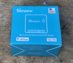
It's time to take a look at the interior of the quite popular, classic Sonoff module with dimensions that fit a typical electrical box. Sonoff Mini R2 is quite cheap - you can buy it for only PLN 30 in our country. Additionally, you can easily change the firmware, although you need to know where GPIO0 is "hidden", which is necessary to put the ESP into flashing mode - but I will explain everything in this topic. So here we go.
Purchase Sonoff MiniR2
The module was purchased by one of my readers. Several units were purchased and I uploaded the firmware to them:
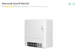
PLN 30 per item. Here are the specifications:
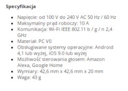
Let's see what we get in the set:
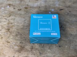
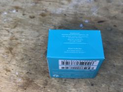
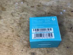
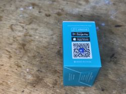
Box contents:
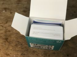
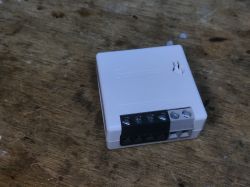
This time they did not provide mounting screws. Unfortunately.
Sonoff Mini R2 interior
We pry the cover and uncover the plate:
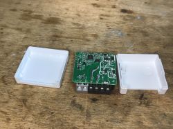
The module is based on ESP8285:
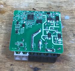
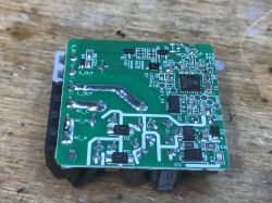
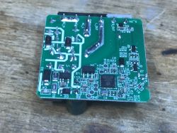
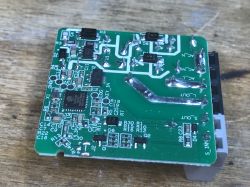
The BP2525 step down converter serves as the power supply, it powers the relay, while the ESP also has an AMS1117-3.3V power supply line on the way:
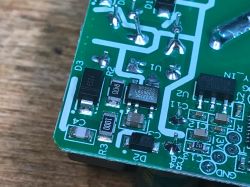
On the top we only have a button, a relay and power supply components (there is even a fuse, varistor and capacitor at the input):
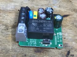
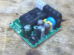
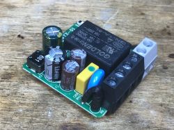
Firmware change
The device is based on ESP8285, so you can load Tasmota via esptool.py . I have discussed this many times, including: here:
SmartLife switch - test, interior and programming of a WiFi light switch
However, in the case of this device, the situation is slightly simplified. because GPIO0 is located on the button .
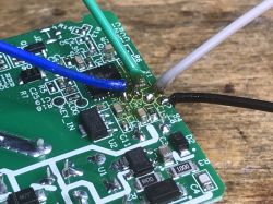
So we solder the power supply (3.3V):
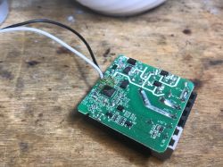
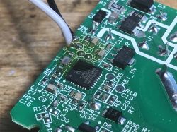
Then RX and TX:
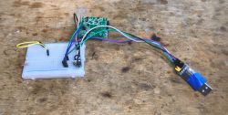
As in previous topics, I have prepared a USB to UART converter, but this time when connecting it to USB, you need to hold the button on the housing so that GPIO0 is shorted to ground while booting ESP. The button can then be released. You can then start programming via esptool.
Tasmota template:
{"NAME":"Sonoff MINIR2","GPIO":[17,0,0,0,9,0,0,0,21,157,0,0,0],"FLAG":0,"BASE":1}GPIO roles:
- GPIO00 - Button1 (the one on the housing)
- GPIO04 - Switch1 (external, connect the switch)
- GPIO12 - Relay1
- GPIO13 - LedLink
What deserves special mention here is the fact that we have a separate LED on a separate GPIO. Sometimes in such devices the LED is only together with the relay and cannot be used separately, e.g. to show the WiFi status.
Summary
Flashing was trouble-free, although without knowing that there was a button on GPIO0, you could have wasted some time figuring out how to put the ESP into programming mode. Apart from that - everything is very good. The price is also really good, combined with free shipping on the website where we bought it, it is a really tempting offer, especially since we receive the products after two days at the parcel locker, and not after 2 weeks from China...
Has anyone built home automation using such Sonoffs? Feel free to comment.


Comments
Information: there is a much simpler way to upload the tape to this device, which does not require opening the case and manual flashing via UART. The instructions are presented in the video: https://www.youtube.com/watch?v=Xn1PmBLFHIM ... [Read more]
Thanks for the information, I thought you were writing about tuya-convert, but this is something new. Valuable post. [Read more]
I have two such devices, bought for PLN 1 in a second-hand textile store. At home, however, I use a Tuya-based ecosystem that does not connect to these switches. Is it possible to install software in ESP... [Read more]
I bought 6 of these switches. They fly great, but they have one problem. When connected to light bulbs or LEDs, you can hear the relay clicking and the light flashing from time to time. I can`t figure... [Read more]