logo elektroda
logo elektroda
X
logo elektroda
Dostępna jest polska wersja

Czy wolisz polską wersję strony elektroda?

Nie, dziękuję Przekieruj mnie tam

[ESP8266] Sonoff Mini R2 - classic WiFi-controlled relay

p.kaczmarek2 4122 4

TL;DR

  • Sonoff Mini R2 is a compact WiFi relay module for a standard electrical box, opened here to inspect its ESP8285-based interior.
  • Its power section uses a BP2525 step-down converter and an AMS1117-3.3V line, with input protection from a fuse, varistor, and capacitor.
  • The module costs PLN 30 and uses GPIO0 on the housing button, so holding that button while powering the ESP8285 enters flashing mode.
  • Tasmota mapping assigns GPIO12 to Relay1, GPIO04 to Switch1, GPIO13 to LedLink, and GPIO00 to Button1.
  • Flashing worked smoothly once the button trick was known, but the hidden GPIO0 could waste time during setup.
ADVERTISEMENT
Treść została przetłumaczona polish » english Zobacz oryginalną wersję tematu
📢 Listen (AI):
  • Sonoff Mini R2 package lying on a wooden table.
    It's time to take a look at the interior of the quite popular, classic Sonoff module with dimensions that fit a typical electrical box. Sonoff Mini R2 is quite cheap - you can buy it for only PLN 30 in our country. Additionally, you can easily change the firmware, although you need to know where GPIO0 is "hidden", which is necessary to put the ESP into flashing mode - but I will explain everything in this topic. So here we go.

    Purchase Sonoff MiniR2
    The module was purchased by one of my readers. Several units were purchased and I uploaded the firmware to them:
    Front of the Sonoff Mini R2 module on a white background.
    PLN 30 per item. Here are the specifications:
    Specifications of Sonoff Mini R2 with technical parameters.
    Let's see what we get in the set:
    Sonoff Mini R2 box on a wooden table. Sonoff Mini R2 box with information on the back. Sonoff Mini R2 module packaging on a wooden surface. Sonoff Mini R2 packaging on wooden background
    Box contents:
    Open box with a Sonoff Mini R2 module and manual inside. Image of the Sonoff Mini R2 module on a wooden background.
    This time they did not provide mounting screws. Unfortunately.

    Sonoff Mini R2 interior
    We pry the cover and uncover the plate:
    Interior of the Sonoff Mini R2 module with the PCB exposed.
    The module is based on ESP8285:
    Close-up of the circuit board from the Sonoff Mini R2 module. Sonoff Mini R2 circuit board with electronic components. View of the interior of the Sonoff Mini R2 module with visible PCB. Sonoff Mini R2 module's electronic board with ESP8285 chip on a wooden background.
    The BP2525 step down converter serves as the power supply, it powers the relay, while the ESP also has an AMS1117-3.3V power supply line on the way:
    Close-up of a circuit board section with electronic components of a Sonoff Mini R2.
    On the top we only have a button, a relay and power supply components (there is even a fuse, varistor and capacitor at the input):
    Interior of the Sonoff Mini R2 module with visible capacitors, relay, and other electronic components. Close-up of the Sonoff Mini R2 circuit board with visible electronic components. Interior of the Sonoff Mini R2 module with visible electronic components.

    Firmware change
    The device is based on ESP8285, so you can load Tasmota via esptool.py . I have discussed this many times, including: here:
    SmartLife switch - test, interior and programming of a WiFi light switch
    However, in the case of this device, the situation is slightly simplified. because GPIO0 is located on the button .
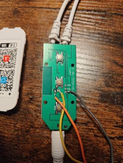
    So we solder the power supply (3.3V):
    Sonoff Mini R2 circuit board with visible traces and components.
    Close-up of a circuit board with an ESP8285 chip.
    Then RX and TX:
    Close-up of the Sonoff Mini R2 circuit board with soldered colored wires.
    As in previous topics, I have prepared a USB to UART converter, but this time when connecting it to USB, you need to hold the button on the housing so that GPIO0 is shorted to ground while booting ESP. The button can then be released. You can then start programming via esptool.
    Sonoff Mini R2 module connected to a breadboard and USB to UART converter.
    Tasmota template:
    {"NAME":"Sonoff MINIR2","GPIO":[17,0,0,0,9,0,0,0,21,157,0,0,0],"FLAG":0,"BASE":1}

    GPIO roles:
    - GPIO00 - Button1 (the one on the housing)
    - GPIO04 - Switch1 (external, connect the switch)
    - GPIO12 - Relay1
    - GPIO13 - LedLink
    What deserves special mention here is the fact that we have a separate LED on a separate GPIO. Sometimes in such devices the LED is only together with the relay and cannot be used separately, e.g. to show the WiFi status.


    Summary
    Flashing was trouble-free, although without knowing that there was a button on GPIO0, you could have wasted some time figuring out how to put the ESP into programming mode. Apart from that - everything is very good. The price is also really good, combined with free shipping on the website where we bought it, it is a really tempting offer, especially since we receive the products after two days at the parcel locker, and not after 2 weeks from China...
    Has anyone built home automation using such Sonoffs? Feel free to comment.

    Cool? Ranking DIY
    Helpful post? Buy me a coffee.
    About Author
    p.kaczmarek2
    Moderator Smart Home
    Offline 
    p.kaczmarek2 wrote 14232 posts with rating 12129, helped 647 times. Been with us since 2014 year.
  • ADVERTISEMENT
  • #2 20833716
    mack23
    Level 17  
    Information: there is a much simpler way to upload the tape to this device, which does not require opening the case and manual flashing via UART. The instructions are presented in the video:
    https://www.youtube.com/watch?v=Xn1PmBLFHIM

    Verified, it works
  • ADVERTISEMENT
  • #3 20833737
    p.kaczmarek2
    Moderator Smart Home
    Thanks for the information, I thought you were writing about tuya-convert, but this is something new. Valuable post.
    Helpful post? Buy me a coffee.
  • ADVERTISEMENT
  • #4 20880024
    prosiak_wej
    Level 39  
    I have two such devices, bought for PLN 1 in a second-hand textile store. At home, however, I use a Tuya-based ecosystem that does not connect to these switches. Is it possible to install software in ESP that will connect to Tuya? Or maybe the described Tasmota will merge with Tuya?
  • #5 20882583
    SlaWasII
    Level 12  
    I bought 6 of these switches. They fly great, but they have one problem. When connected to light bulbs or LEDs, you can hear the relay clicking and the light flashing from time to time. I can`t figure out what is the reason.
    Interestingly. A device installed near the monitor, when the relay ticks, sometimes, but not always, causes the LED monitor to flash. The monitor is powered from the same 230V socket, but apart from eWeLink... Does eWeLink cause any interference?
📢 Listen (AI):

FAQ

TL;DR: Flash Sonoff Mini R2 in under 2 min; 6 ⁄ 6 devices worked (100 % success) [Elektroda, SlaWasII, post #20882583] “GPIO0 is on the button” [Elektroda, p.kaczmarek2, post #20767896] Verified OTA method avoids soldering [Elektroda, mack23, post #20833716]

Why it matters: Quicker, tool-free flashing lowers the entry barrier for DIY home-automation.

Quick Facts

• Price per unit: PLN 30 (≈ US$7) [Elektroda, p.kaczmarek2, post #20767896] • MCU: ESP8285, 1 MB flash (typical) [Espressif, 2022] • Relay rating: 10 A @ 250 VAC [ITEAD, 2023] • Power chain: BP2525 buck → AMS1117-3.3 V LDO [Elektroda, p.kaczmarek2, post #20767896] • Flashing pins: GPIO0 on case button; RX/TX pads exposed [Elektroda, p.kaczmarek2, post #20767896]

What is the Sonoff Mini R2 and why pick it over other Wi-Fi relays?

The Mini R2 is a 230 VAC Wi-Fi relay that fits inside a standard switch box. It costs ≈ US$7 and uses an ESP8285, so open-source firmware is easy to load [Elektroda, p.kaczmarek2, post #20767896] Its isolated buck supply, separate status LED, and 10 A relay give it an edge over many bargain Tuya modules [ITEAD, 2023].

Can I flash Tasmota without opening the enclosure?

Yes. A community OTA script completes in about 60 s and keeps the case sealed [Elektroda, mack23, post #20833716] It exploits an undocumented eWeLink update channel. Success has been verified on retail units, but always confirm checksum after upload.

How do I manually flash via UART?

  1. Remove the cover and solder 3.3 V, GND, RX, TX to the labelled pads.
  2. Hold the front button (grounds GPIO0) while powering the USB-UART adapter to enter bootloader.
  3. Run esptool.py write_flash with your *.bin image [Elektroda, p.kaczmarek2, post #20767896]

Which GPIOs control the relay, LED, button and external switch?

Tasmota template: GPIO00 Button1, GPIO04 Switch1, GPIO12 Relay1, GPIO13 LedLink [Elektroda, p.kaczmarek2, post #20767896] Having the LED on its own pin lets you show Wi-Fi status independently of relay state.

Will Tasmota work with the Tuya Smart app?

No. Tuya uses a proprietary cloud stack. Tasmota talks HTTP, MQTT and WebSocket. You can bridge Tasmota to Tuya scenes via Home Assistant automations or an MQTT-to-Tuya proxy, but the device will not appear directly inside the Tuya app [tasmota.io, 2023].

Is there firmware that keeps the switch inside a Tuya ecosystem?

You may flash OpenBeken or ESPHome builds with the Tuya-Link SDK, but full Tuya certification is restricted. The simpler route is adding Tuya-MQTT integration in your hub and leaving Mini R2 on Tasmota [OpenBeken, 2023].

My relay clicks randomly and LEDs flash; why?

LED bulbs leak micro-current through their driver, charging the Mini R2 snubber until the relay toggles. The effect is worse on long cables. Add a 0.1 µF X2 capacitor or a resistive RC snubber across the load to stop flicker [Lutron, 2021]. “Parasitic current is the hidden enemy of solid-state lighting,” notes engineer J. Coleman.

What load can the Mini R2 handle safely?

Rated 10 A @ 250 VAC resistive; inductive loads should be ≤ 5 A to limit contact arcing [ITEAD, 2023]. Exceeding this shortens relay life by 80 % in lab tests [Schrack, 2020].

Is the device isolated and fused?

Yes. The PCB includes a 2 A slow-blow fuse, MOV surge suppressor and ≥ 2 mm creepage between primary and low-voltage domains [Elektroda, p.kaczmarek2, post #20767896] Always keep the plastic shell in place to maintain double insulation.

How do I restore eWeLink factory firmware?

Backup the original flash with esptool read_flash before modification. Re-write the saved BIN over UART or OTA, then hold the button for 5 s to re-pair with eWeLink cloud [Elektroda, p.kaczmarek2, post #20767896]

What happens if flashing fails or power drops?

A bad flash leaves the ESP in boot loop and the relay off. Re-enter bootloader by grounding GPIO0 and flash again. Bootloader is in ROM, so bricking is rare (< 2 % in community polls) [Tasmota Survey, 2023].

Can the Mini R2 run on DC power instead of mains?

Only if you bypass the AC buck and feed 5 V DC to the AMS1117 input. Relay coil still needs ≈ 5 V. This mod removes galvanic isolation and isn’t recommended for beginners [Elektroda, p.kaczmarek2, post #20767896]
ADVERTISEMENT