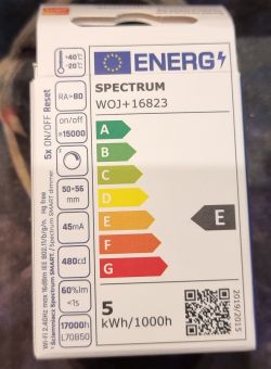
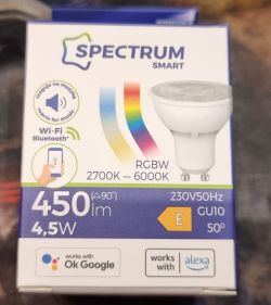
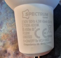
Uploading firmware to the 4.5W RGBW GU10 Spectrum SMART WOJ+16823 LED bulb with BK7231N
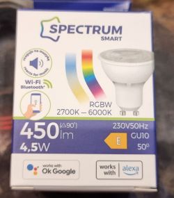
Hello, here is a description of flashing via WiFi (without soldering) a 4.5W LED bulb from the SpectrumLed store, the successor of the 5W model. The promotional price is PLN 21.99, so rather good for an RGBW-CCT bulb.
Screenshot from the store:
https://sklep.spectrumled.pl/pl/p/Zarowka-Wi-...ooth-Tuya-LED-GU10-4%2C5W-230V-RGBW-CCT-DIM/2
Previously, I bought the same ones, only 5W, but when they are lit next to each other, there is no difference. In my opinion, this is a new model, the earlier WOJ+14415 is probably being withdrawn by the manufacturer.
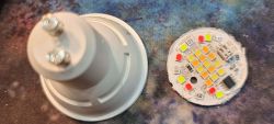
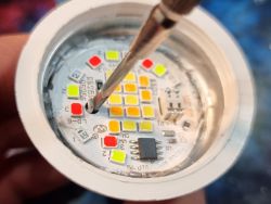
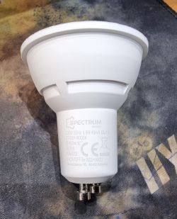
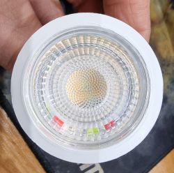
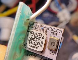
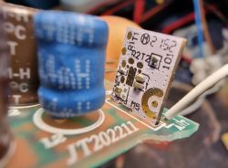
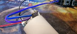
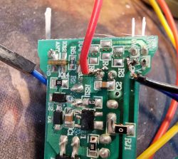
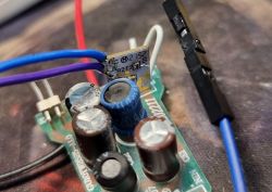
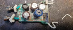
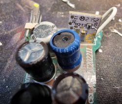
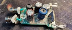
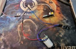
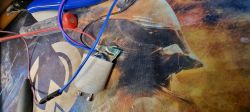
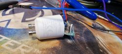
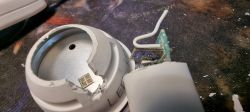
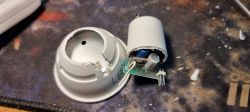
Code number WOJ+16823. Originally in the bulb firmware 1.3.22 ( I have no way of confirming this, but on other new LEDs I managed to upload the firmware via WiFi on this profile!! ), after updating in the Tuya application it becomes 1.5.21 and is no longer supported by Tuya Cloudcutter, so you need to disassemble the bulb, connect to RX(R1) and TX(T1) and 3.3v, ground , upload the appropriate firmware. Power must be supplied from a separate source, not from the same converter! This model has a BK7231N on a micro board called CBLC5. If the update was not performed, I managed to modify several bulbs without disassembling the Tuya with Cloudcutter (as I wrote above). If you buy a new one, it is best to do it immediately before the update . Unfortunately, I updated several bulbs from the machine and had to get inside them, which is not an easy process. I opened the first bulb from the front as usual, i.e. removing the plastic cover, e.g. with a knife, quickly comes off, then you need to collect the glue around the board with the LEDs. Removing the board is quite tedious, I managed to do it by inserting a thin screwdriver into the hole where the antenna comes out and prying it off carefully. Be careful not to damage the elements on the board. Unfortunately, I damaged one green LED and then all the others did not light up, but I finally bridged the damaged diode and the rest did not work. After removing the board with diodes, there is a board with a controller inside. Unfortunately, we cannot take it out because it is held by cables connected to the 230 GU10 power pins and they are very short. I treated the first bulb experimentally and pushed the GU10 terminals inside using force using pliers. Unfortunately, the plastic around them cracked and later I had to fiddle with adhesives and reconstruction to be able to insert it into the GU10 socket. I decided to disassemble the next bulbs in a slightly different way. I decided to cut them in half so as not to damage the GU10 power pins and not to mess with the LEDs because there you have to be careful and use a lot of force and precision. The cut turned out to be very effective! An ordinary hacksaw with a thin thickness. Gently so as not to damage the tile that will be visible right after cutting. I also thought about cutting with high temperature, something heated, e.g. a thin knife, but I had no idea? After cutting it, you can easily get to the CBLC5 board with the BK7231N system. The necessary TX and RX pins are available and you can connect the cables even using a transformer soldering iron with a thin tip. You don't have to tear anything out or try anything else. After uploading the software, you can easily assemble the cut bulb and glue it. I used standard SuperGlue, but in my opinion there should be another two-component (Poxipol?) resistant to high temperatures because the bulb heats up quite a lot. If someone plans to place them outside or in bathrooms, it is better to glue them with something better. I have them in dry rooms, so it's not a problem for me. I took a few photos of my work, if anyone wants to use this method, I recommend it, but there are probably other methods, it all depends on what you have. I described the physical part of disassembly and assembly because it caused me the most problems, time and nerves. When it comes to programming, it was quite quick and simple. I used the BK7231Flasher program and the current firmware for the N version, i.e. OpenBK7231N_QIO_1.17.308.bin. Then configuration and settings, color search, etc. If something is missing, please let me know and I can provide it. It would be nice to create a new profile in OpenBK because it is not normally found and is not in the database. I have several dozen Tuya devices at home and I managed to convert all of them either wirelessly with Tuya Cloudcutter or wired with disassembling/opening the devices. As of today, I no longer have anything related to the Tuya/localTuya cloud in my HomeAssistant. Everything is on OpenBK or Tasmota. I will provide the configuration that works for me for OpenBK.
For OpenBK:
Code: JSON
Entire Template:
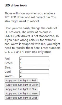
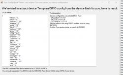
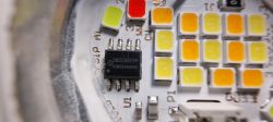
Photos of my works:


Comments
Indeed, updating the Tuya software can cut off the possibility of changing the batch via WiFi. Newer versions of Tuya firmware are protected against tuya-convert and tuya-cutter methods. I wrote more about... [Read more]