Manhot Store's BK7231N / CB3S Tuya Smart 4 Gang Switch: WiFi not Zigbee, CB3S Chip Inside
I've bought a wall switch from Manhot Store in aliexpress with 4 "clicky" buttons.
AliExpress link: https://www.aliexpress.com/item/1005005901971631.html
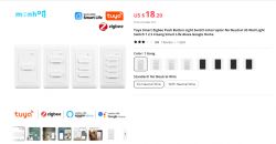
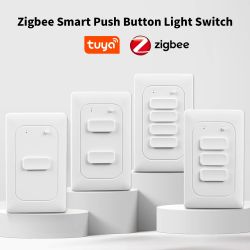
The device is listed as a Zigbee Smart switch, but it's actually a WiFi switch!! with a CB3S chip inside.
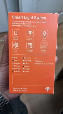
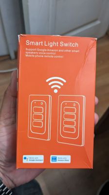
Now the fun part!
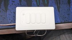
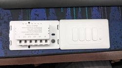
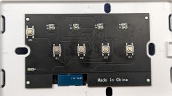
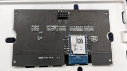
Regarding functionality, when a button is pressed, the corresponding relay is triggered.
The button has a light that shows whether the relay is open or closed - it will show up as orange when the relay is ON and blue when the relay is OFF.
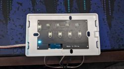
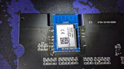
The device is powered by a CB3S chip, although not all of its pins are soldered on the PCB. Upon checking the datasheet for the MCU, we can determine the required pins to flash the device:
Datasheet: https://developer.tuya.com/en/docs/iot/cb3s?id=Kai94mec0s076
Soldered a small wire to the CEN pin to put the device into bootloader mode in order to flash a new firmware.
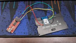
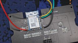
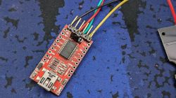
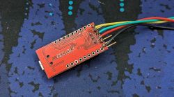
I was able to flash OpenBK using the new BK7231GuiFlashTool and the OpenBK7231N_QIO_1.17.308.bin firmware under windows, but no luck using the flash tool under linux (ubuntu).
I've attached the original .json device template.
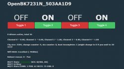
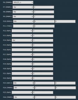
This is the actual OpenBK pin configuration of the module.
Now only the orange led turn on when the relay is on, but the blue light doesn't work. it's fine...
AliExpress link: https://www.aliexpress.com/item/1005005901971631.html


The device is listed as a Zigbee Smart switch, but it's actually a WiFi switch!! with a CB3S chip inside.


Now the fun part!


Regarding functionality, when a button is pressed, the corresponding relay is triggered.
The button has a light that shows whether the relay is open or closed - it will show up as orange when the relay is ON and blue when the relay is OFF.
The device is powered by a CB3S chip, although not all of its pins are soldered on the PCB. Upon checking the datasheet for the MCU, we can determine the required pins to flash the device:
Datasheet: https://developer.tuya.com/en/docs/iot/cb3s?id=Kai94mec0s076
Soldered a small wire to the CEN pin to put the device into bootloader mode in order to flash a new firmware.
| Pin Name | Pin Number |
| CEN | 3 |
| VCC | 8 |
| GND | 9 |
| RX1 | 15 |
| TX1 | 16 |


I was able to flash OpenBK using the new BK7231GuiFlashTool and the OpenBK7231N_QIO_1.17.308.bin firmware under windows, but no luck using the flash tool under linux (ubuntu).
I've attached the original .json device template.
This is the actual OpenBK pin configuration of the module.
| Pin | Type | Channel | P6 | WifiLED_n | - | P7 | Relay | 4 | P8 | Relay | 3 | P9 | Relay | 2 | P10 | Button | 4 | P14 | Relay | 1 | P23 | Button | 3 | P24 | Button | 2 | P26 | Button | 1 |
Now only the orange led turn on when the relay is on, but the blue light doesn't work. it's fine...


Comments
Thanks for the review. That's very strange, you got a WiFi version instead of Zigbee, you should get a refund! Regarding the template, can you also add GPIO in a form of OBK template from the Web App? EDIT:... [Read more]
Hi! Playing a bit with the GPIO finder i've dicovered that PIN 11 controls the BLUE LEDS. Selecting "LED" for pin 11 turns on the blue LEDs when the relay is off. when the relay is on, le blue leds... [Read more]
That's interesting and very useful. By the way, If you want a permanent setting, you can change LED_n to AlwaysHigh or AlwaysAll. [Read more]
Thanks for the tip!! I'm trying to find the way to get the opposite behaviour of the leds. blue when the relay is on and orange when is off. my other light switches work that way and is more intuitive,... [Read more]
What about the reset button at the top, what is the pin number? [Read more]
Whoa, very good question! It seems that we've missed one pin: https://obrazki.elektroda.pl/1440584900_1719312080_thumb.jpg It seems I need to add backlit_io_pin to our flasher soon. [Read more]
Any progress on finding that missing pin? [Read more]
As I said, have you tried P11? [Read more]
GPI013 [Read more]
I can't see this particular GPIO in the JSON. Can you try getting Tuya binary (Web App -> Flash tab) and attach it here so I can investigate if it was correctly extracted? [Read more]
yes. I have a Tuya device with 3 LEDs and this in the keys. "backlit_io_pin": 23 Device configuration, as extracted from Tuya: - Button (channel 1) on P20 - LED (channel 1) on P26 - WiFi... [Read more]
Isn't it already added? https://github.com/search?q=repo%3Aopenshwprojects%2FBK7231GUIFlashTool%20backlit_io_pin&type=code Or maybe I need to add a build... [Read more]
ah yes. a few commits not in June 5th build it seems [Read more]
https://obrazki.elektroda.pl/7361657300_1732440883_thumb.jpg https://obrazki.elektroda.pl/5401697800_1732440934_thumb.jpg cool I've rather presumptuously given it a version of 1.3.4 [Read more]