FAQ
TL;DR: 96 % of DIY flashes drop idle power from 12 W to 2–3 W [Elektroda, abaku, post #21450881] “Drill the six plastic rivets first” [Elektroda, flobuljeedom, post #20842835] Map P7/P26 to BridgeFWD/REV to stop negative wattage [Elektroda, flobuljeedom, post #20957977]
Why it matters: Proper pin mapping and calibration prevent heat-related failures and give accurate energy data.
Quick Facts
• MCU: Beken BK7231N, 120 MHz, 2 MB flash [Elektroda, flobuljeedom, post #20842835]
• Energy IC: BL0942, 0.5 % typical accuracy [BL0942 datasheet]
• Default relay pulse: 60 ms (rl1_drvtime) [Elektroda, Tuya dump, post #20842835]
• Stand-by draw after fix: 2.4 W @ 230 V [Elektroda, abaku, post #21450881]
• Street price: USD 15–18 on AliExpress (Feb 2025) [AliExpress listing]
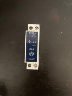
What components are inside the EARU EAWCPT-J?
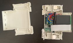
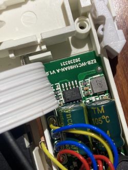
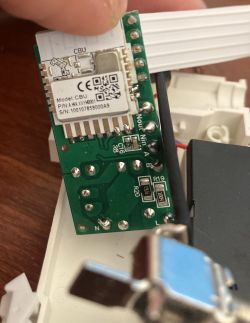
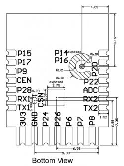
The board carries a CBU Wi-Fi module with a BK7231N SoC, a BL0942 energy-measurement chip, opto-drivers for the bistable relay, and two panel LEDs [Elektroda, flobuljeedom, post #20842835]
How do I open the enclosure cleanly?
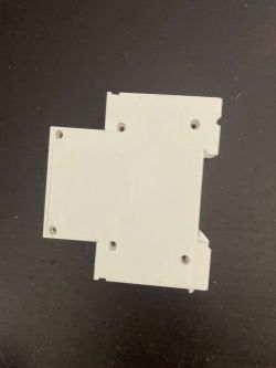
Drill out the six plastic rivets (Ø 3 mm works). Push the stubs inwards, then pry the shell apart with a thin spudger. “Drill the six plastic rivets first” [Elektroda, flobuljeedom, post #20842835]
Which GPIO mapping works for the rear-mounted CBU revision?
Use:
• P6 → LED_n ch1
• P7 → BridgeFWD ch1
• P8 → WifiLED_n
• P15 → Btn ch1
• P26 → BridgeREV ch1 [Elektroda, abaku, post #21454550]
Why were power and power-factor negative when the relay was OFF?
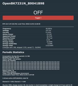
The BL0942 saw current flowing opposite to the expected direction. Re-assigning P24 and P26 to BridgeFWD/REV corrected polarity and the readings became positive [Elektroda, flobuljeedom, post #20957977]
GUI BK7231Flasher fails; what is a reliable alternative?
Run the Python “obsolete” uartprogram script:
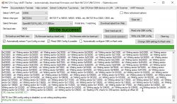
python3 uartprogram OpenBK7231N_QIO_1.17.621.bin --unprotect -d /dev/ttyUSB0 -w --startaddr 0x0
Users report consistent success after the GUI write error [Elektroda, imarin2, post #21127569]
How can I re-close the housing after drilling?
Thread the empty rivet sleeves with small screws. M3 × 12 mm or even M1.5 × 12 mm bolts grip well and restore stiffness [Elektroda, flobuljeedom, #21127574; Elektrode, imarin2, #21127603].
My unit still draws 12 W idle—how do I fix that?
Enable Wi-Fi PowerSave (PowerSave 1), verify BridgeFWD/REV roles, and recalibrate BL0942. After these steps users measured 2–3 W at 230 V [Elektroda, abaku, post #21450881]
How do I calibrate voltage, current, and power in OpenBK?
- Connect a known resistive load (≈40 W bulb).
- Open Tools → Calibration and enter actual meter values.
- Click Apply; internally VoltageSet, CurrentSet, PowerSet are issued [Elektroda, p.kaczmarek2, post #21450890]
Is there a hardware revision with different pins?
Yes. Mid-2024 boards moved the CBU module to the front. Pinout became P7/P26 relay, P9 panel LED, P15 button, and the red Wi-Fi LED was hard-wired to 3.3 V [Elektroda, theunknown, post #21281181]
BridgeFWD/REV do not latch the relay—what can I try?
Power-cycle after assigning roles so the Bridge driver loads [Elektroda, theunknown, post #21281181] If it still fails, increase pulse width: set RelayPulse_ms 100 for a stronger kick.
Can I keep Tuya settings after flashing OpenBK?
Yes. The Tuya partition is untouched unless you perform a full-chip erase. Use Tuya-Dump in Web Tools to import pins and thresholds automatically [Elektroda, p.kaczmarek2, post #21449943]
Quick 3-step flashing guide
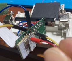
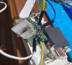
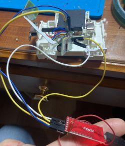
- Solder—or needle-probe—RX, TX, 3V3, GND to the CBU header.
- Run uartprogram with --unprotect and write OpenBK firmware.
- Reboot, then import the JSON template and power-cycle. (Total time ≈5 min).
Edge case: factory firmware read stops at 0x40000—what now?
Lower baud to 115 200 and retry. Some chips timeout at higher rates. Even if read fails, writing OpenBK still works [Elektroda, daxliniere, post #21198102]
Is the ‘63 A’ label real?
Testing shows enclosure and relay warm above 20 A; at 60 °C case temperature was logged with only idle load [Elektroda, abaku, post #21447757] Treat 20 A as a safe continuous limit.
Where can I get a ready template?
The latest JSON templates for both board revisions are in post #1 and #20 of the thread; copy into OpenBK’s Template page and click Apply [Elektroda, abaku, post #21454550]




Comments
Concerning the issue with negatives/positives values when relay is OFF, I figured it out. I changed pins 24 and 26 to "BridgeFWD" and "BridgeREV". Updated template as well. [Read more]
Hello @flobuljeedom, how did you opened and closed it without broken it? I open mine forcing the plastic and the final result was not very good. I have no idea how to close it without tape :). [Read more]
As I wrote, drill it [Read more]
Thank you. The GUI Flash app did not work for me. It ended with write failure. However, the python "obsolete" method worked fine: python3 uartprogram OpenBK7231N_QIO_1.17.621.bin --unprotect... [Read more]
I used M3 screws and bolt I had in my drawer [Read more]
Nice idea. I had a couple of M1.5 bolts around (12mm long). They fit tight inside the hole of the drilled rivets. So I used them to thread the inside of the rivets (so one side you see the original... [Read more]
Hey @flobuljeedom, thanks so much for posting this. I have flashed with your config file, but for some reason the red LED which should be 'mains power present' is illuminated (it also flashes during bootup)... [Read more]
Ich have trouble to switch the the bistable relay in this device. I have definde the output pins as BridgeFWD and BridgeRE (like the JSON in this thread) "24": "BridgeFWD;1", "26":... [Read more]
***CBU MODULE ON THE BACK? CHECK FIRST POST*** ***CBU MODULE ON THE FRONT? SEE BELOW*** It seems there has been a hardware revision for the EAWCPT-J. The CBU module is now on the front of the board,... [Read more]
I have just received the EAWCBT-J I'm assuming it's from current production, internally it looks identical to post #10, I uploaded OpenBK7231N using BK7231Flasher, I didn't solder - I used acupuncture... [Read more]
If you used this template: "pins": { "6": "LED_n;1", "7": "Btn;1", "8": "WifiLED_n;0", "24": "BridgeFWD;1", "26": "BridgeREV;1" }, ... [Read more]
Hello, thank you for your reply and above all for what you are doing for open source yes i used this template, i didn't manage to archive the original configuration but i will measure from nature which... [Read more]
. But nothing needs to be archived here. The Tuya config partition is still there after flashing. It is not deleted. As long as you don't deliberately perform a 2MB erase of the entire flash then it doesn't... [Read more]
measurement with meter ~10mA ~240V = 2.4W and indicates 12W tuya configuration: (never been added to the cloud) { "bt1_pin": "15", "led1_pin": "6", "rl1_drvtime": "60", "net_trig":... [Read more]
Do you know about the calibration process? As in Tasmot. VoltageSet, CurrentSet, PowerSet commands. Also you can through the Web App under Tools, there is a ready form there. [Read more]
I did according to the indicated video tutorial and .... in web application/import generated such a script: clearIO // clear old GPIO/channels lfs_format // clear LFS StartupCommand "" // clear... [Read more]
Thanks for pointing this out - I see that on the Web App the importer did not have bridge relay implemented. Only on the windows app was it entered. I have corrected it: https://obrazki.elektroda.pl/8598134300_1740387701_bigthumb.jpg... [Read more]
EARU EAWCPT-J In this version (delivery 02.2025), the location of the LED POWER and LED WIFI is changed https://obrazki.elektroda.pl/7131103900_1740038535.jpg working template: { "vendor": "Tuya", ... [Read more]
Thanks for the template, but if you can put it in a syntax json tag. Is everything working now? How about the power consumption? As for the LED, it's at your discretion - some want it to light up... [Read more]