logo elektroda
logo elektroda
X
logo elektroda

[BK7231N / WC1H] EARU DIN Rail relay EAWCPT-J (with energy meter)

flobuljeedom 8193 22
ADVERTISEMENT
  • This is my teardown of EARU EAWCPT-J relay.
    35mm Din Rail WIFI Smart Switch Remote control byTuya APP for Smart home from https://fr.aliexpress.com/item/1005005903760507.html
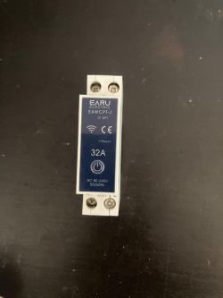
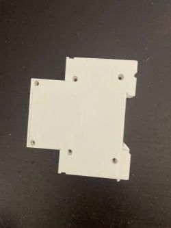
    EARU EAWCPT-J WiFi Smart Switch for DIN Rail View of the back part of a white DIN rail relay housing.

    First, drill the 6 holding "screws" and push them through. And split the shields.
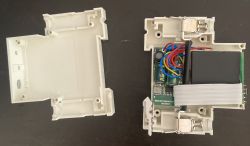
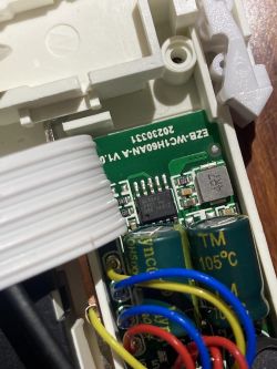
    Disassembled smart WIFI relay for DIN rail.

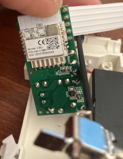
    WC1H - BL0942 - CBU :
    Close-up of the interior of a relay housing showing electronic components, including capacitors and a microchip. Close-up of an electronic module labeled CBU on a circuit board.

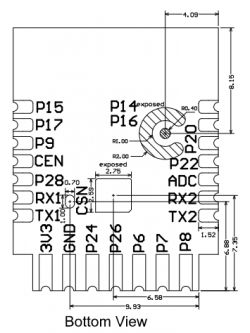
    From CBU pins :
    Bottom view schematic of the PCB with pin numbering and dimensions.

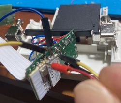
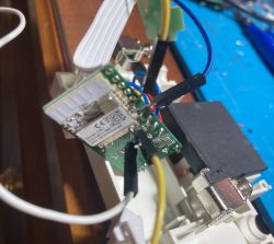
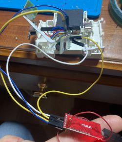
    Soldered to RX1, TX1, 3V3 and GND and connected to FTDI232 :
    The image shows a USB FTDI adapter with attached wires and a glowing LED. Close-up view of the internal components of a WiFi smart switch on a Din rail. EARU relay board with wired connections EARU EAWCPT-J relay circuit with connected FTDI232 module.

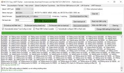
    Reading only worked with 9600 baud rate :
    BK7231 Easy UART Flasher software interface with visible operation log. Screenshot of BK7231 Easy UART Flasher showing successful firmware write.

    json and configuration extracted:
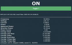
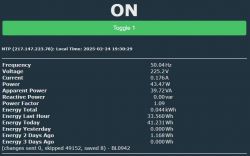
    Code: JSON
    Log in, to see the code


    Code: Text
    Log in, to see the code


    My current template:
    Code: JSON
    Log in, to see the code


    Startup command:
    Code: Text
    Log in, to see the code


    I then calibrated Voltage, Current and Power.
    Just one issue, when relay is down, "Active Power" and "Power Factor" indicate negative value, even with Flag 38 checked.
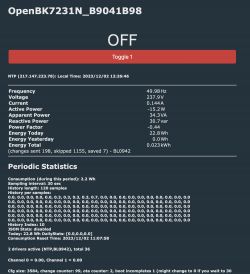
    Screenshot of the OpenBK7231N user interface displaying relay information.


    Here is the original firmware backup: readResult...-50-33.bin Download (2 MB)

    Cool? Ranking DIY
    About Author
    flobuljeedom
    Level 7  
    Offline 
    flobuljeedom wrote 16 posts with rating 85, helped 1 times. Live in city Paris. Been with us since 2023 year.
  • ADVERTISEMENT
  • #2 20957977
    flobuljeedom
    Level 7  
    Concerning the issue with negatives/positives values when relay is OFF, I figured it out.

    I changed pins 24 and 26 to "BridgeFWD" and "BridgeREV".

    Updated template as well.
  • #3 21071448
    brunovier
    Level 1  
    Hello @flobuljeedom, how did you opened and closed it without broken it? I open mine forcing the plastic and the final result was not very good. I have no idea how to close it without tape :).
  • #4 21071486
    flobuljeedom
    Level 7  
    flobuljeedom wrote:
    First, drill the 6 holding "screws" and push them through.

    As I wrote, drill it
  • #5 21127569
    imarin2
    Level 2  
    Thank you.

    The GUI Flash app did not work for me. It ended with write failure.

    However, the python "obsolete" method worked fine:

    python3 uartprogram OpenBK7231N_QIO_1.17.621.bin --unprotect -d /dev/ttyUSB0 -w --startaddr 0x0


    It is the third method in this page:
    https://github.com/openshwprojects/OpenBK7231T_App/blob/main/FLASHING.md

    Any idea how to replace the drilled rivets after flashing? The structural integrity is decreased without them.
  • ADVERTISEMENT
  • #6 21127574
    flobuljeedom
    Level 7  
    I used M3 screws and bolt I had in my drawer
  • #7 21127603
    imarin2
    Level 2  
    Nice idea.

    I had a couple of M1.5 bolts around (12mm long). They fit tight inside the hole of the drilled rivets. So I used them to thread the inside of the rivets (so one side you see the original rivet, the non-drilled end, and the other side the M1.5 bolt head). They secure well and looks quite good.
  • #8 21198102
    daxliniere
    Level 1  
    Hey @flobuljeedom, thanks so much for posting this.
    I have flashed with your config file, but for some reason the red LED which should be 'mains power present' is illuminated (it also flashes during bootup) and the pushbutton doesn't cause the relay to trigger.
    However, I can confirm that with the device's web controls, I am able to toggle the relay and the green 'relay active' LED works as expected.

    I can confirm that the device is the same, though the writing of the word "ELECTRIC" is very slightly different.

    Update: I used the GPIO Doctor and determined that the button is correctly connected and working, but as I mentioned, it's not activating the relay.

    Added after 10 [hours] 28 [minutes]:

    Another update: After reinstalling, I can confirm that the device is working as expected.

    Added after 5 [minutes]:

    Interestingly, I'm attempting to flash another unit that I bought about a month later (visually identical) and it keeps failing on the firmware read step. I have slowed it down from 921600 to 115200, but no luck. I'm glad I was lucky enough to have started with a fully working unit as I may not have attempted to modify the second unit.

    I can confirm, however, that I was able to flash the OpenBK firmware without issues, even though I couldn't read the factory firmware without error.

    
    Starting read backup and flash new!
    Now is: 21 August 2024 10:07:45 AM.
    Flasher mode: BK7231N
    Going to open port: COM4.
    Serial port open!
    Getting bus... (now, please do reboot by CEN or by power off/on)
    Getting bus success!
    Going to set baud rate setting (115200)!
    Will try to read device flash MID (for unprotect N):
    Flash MID loaded: 1560EB
    Will now search for Flash def in out database...
    Flash def found! For: 1560EB
    Flash information: mid: 1560EB, icName: TH25Q_16HB, manufacturer: TH, szMem: 1000000, szSR: 2, cwUnp: 0, cwEnp: 7, cwMsk: 407C, sb: 2, lb: 5, cwdRd: 05-35-FF-FF, cwdWr: 01-FF-FF-FF
    Entering SetProtectState(True)...
    sr: 0
    sr: 0
    final sr: 0
    msk: 407c
    cw: 0, sb: 2, lb: 5
    bfd: 0
    SetProtectState(True) success!
    Going to read encryption key...
    Encryption key read done!
    Encryption key: 510fb093 a3cbeadc 5993a17e c7adeb03
    Going to start reading at offset 0x00...
    Reading 0x00... Ok! Reading 0x1000... Ok! Reading 0x2000... Ok! Reading 0x3000... Ok! Reading 0x4000... Ok! Reading 0x5000... Ok! Reading 0x6000... Ok! Reading 0x7000... Ok! Reading 0x8000... Ok! Reading 0x9000... Ok! Reading 0xA000... Ok! Reading 0xB000... Ok! Reading 0xC000... Ok! Reading 0xD000... Ok! Reading 0xE000... Ok! Reading 0xF000... Ok! Reading 0x10000... Ok! Reading 0x11000... Ok! Reading 0x12000... Ok! Reading 0x13000... Ok! Reading 0x14000... Ok! Reading 0x15000... Ok! Reading 0x16000... Ok! Reading 0x17000... Ok! Reading 0x18000... Ok! Reading 0x19000... Ok! Reading 0x1A000... Ok! Reading 0x1B000... Ok! Reading 0x1C000... Ok! Reading 0x1D000... Ok! Reading 0x1E000... Ok! Reading 0x1F000... Ok! Reading 0x20000... Ok! Reading 0x21000... Ok! Reading 0x22000... Ok! Reading 0x23000... Ok! Reading 0x24000... Ok! Reading 0x25000... Ok! Reading 0x26000... Ok! Reading 0x27000... Ok! Reading 0x28000... Ok! Reading 0x29000... Ok! Reading 0x2A000... Ok! Reading 0x2B000... Ok! Reading 0x2C000... Ok! Reading 0x2D000... Ok! Reading 0x2E000... Ok! Reading 0x2F000... Ok! Reading 0x30000... Ok! Reading 0x31000... Ok! Reading 0x32000... Ok! Reading 0x33000... Ok! Reading 0x34000... Ok! Reading 0x35000... Ok! Reading 0x36000... Ok! Reading 0x37000... Ok! Reading 0x38000... Ok! Reading 0x39000... Ok! Reading 0x3A000... Ok! Reading 0x3B000... Ok! Reading 0x3C000... Ok! Reading 0x3D000... Ok! Reading 0x3E000... Ok! Reading 0x3F000... Ok! Reading 0x40000... failed with serial.BytesToRead 0 (expected 4111)
    The beginning of buffer in UART contains  data.
    Failed! 
    
  • #9 21240520
    Agetommy
    Level 1  
    Ich have trouble to switch the the bistable relay in this device. I have definde the output pins as BridgeFWD and BridgeRE (like the JSON in this thread)

     "24": "BridgeFWD;1",
    "26": "BridgeREV;1"


    With this definition the Relay will not switch.

    In case i define the same pins as "Relay"

     "24": "Relay;1",
    "26": "Relay_n;1"


    The relay switching is OK. But with the disadvantage that the relay coils have permanent power and the DIN Relay consumpt permanemt 6W and get very warm

    My my suspicion is, the short peak to power a coil of the bistable relay, ist to short. Is it possible to extend the peaktime? Or do you have a other suspect regarding the cause of this issue?

    I had tested version 1.17.728 (latest today) and 1.17.698.
  • #10 21281181
    theunknown
    Level 1  
    ***CBU MODULE ON THE BACK? CHECK FIRST POST***
    ***CBU MODULE ON THE FRONT? SEE BELOW***


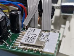
    It seems there has been a hardware revision for the EAWCPT-J. The CBU module is now on the front of the board, the pinout has changed slightly and the manufacturer made an error with with Red WiFi LED as it's now wired directly to 3.3v rather than GPIO of the module which results in it being on constantly.
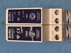
    Two EAWCPT-J modules with WiFi label and 16A power rating

    The text output from the Tuya Config on the new module is below. You'll note they mapped P9 to WiFi LED when it should be the Relay LED.

    - Button (channel 1) on P15
    - Bridge Relay On (channel 1) on P7
    - Bridge Relay Off (channel 1) on P26
    - WiFi LED on P9


    This pinout map below will make the module work, but the Red WiFi LED will be on constantly.
    "7": "BridgeFWD;1",
    "9": "LED_n;1",
    "15": "Btn;1",
    "26": "BridgeREV;1"


    To fix the Red WiFi LED problem you need to de-solder the middle conductor from the front panel ribbon and solder it directly to P8 on the CBU module as below.
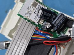
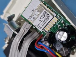
    Close-up of an electronic module labeled CBU with visible wiring. Close-up of a CBU module on a circuit board with wires. Close-up of a CBU module on a circuit board.

    Then use this config to get full functionality including the WiFi LED fix
    "7": "BridgeFWD;1",
    "8": "WifiLED_n;0",
    "9": "LED_n;1",
    "15": "Btn;1",
    "26": "BridgeREV;1"


    Added after 3 [minutes]:

    >>21240520 @Agetommy

    You need to power cycle the device after setting BridgeFWD/REV so the Bridge module can be loaded. I had that same problem.
  • ADVERTISEMENT
  • #11 21447757
    abaku
    Level 11  
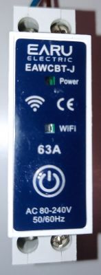
    I have just received the EAWCBT-J
    I'm assuming it's from current production, internally it looks identical to post #10, I uploaded OpenBK7231N using BK7231Flasher, I didn't solder - I used acupuncture needles. I used the configuration template from post #1.
    Compared to those shown, the location of the POWER and WIFI LEDs has changed.
    After commissioning, the POWER LED actually indicates the ON/OFF relay status, but I can only control from the web interface, the button on the panel is dead, the WIFI LED is on continuously.
    EAWCBT-J module by Earu Electric with visible Power and WiFi indicators.
    .

    another problem is the high power consumption, about 12W, obviously with no load, whether the relay is ON or OFF. As a consequence the circuit gets very hot >60°C.

    Screenshot of a web interface showing power data of a device.
    .

    How to start full functionality and restore safety (temeperature) and efficiency (power consumed) of EAWCBT-J ?
  • #12 21448091
    p.kaczmarek2
    Moderator Smart Home
    If you used this template:
    
    
      "pins": {
        "6": "LED_n;1",
        "7": "Btn;1",
        "8": "WifiLED_n;0",
        "24": "BridgeFWD;1",
        "26": "BridgeREV;1"
      },
    
    .
    And the physical button (Btn on pin 7 with channel 1) doesn't work, but switching from the web panel works, it's more likely that pin 7 is simply not a button. The button must be on a different pin. Do an extraction of the Tuya configuration:
    https://www.youtube.com/watch?v=WunlqIMAdgw

    This 12W was measured with an external meter?

    As long as the Bridge is configured correctly, it shouldn't draw much power. Maybe there is something else wrong?

    What do you mean by "safety (temperature)"?
    Helpful post? Buy me a coffee.
  • #13 21449870
    abaku
    Level 11  
    Hello,
    thank you for your reply and above all for what you are doing for open source
    yes i used this template, i didn't manage to archive the original configuration but i will measure from nature which pin the manual control contactor goes to
    I haven't yet measured the current consumption with an external meter but of course I plan to do so for confirmation of measurements/calibration - the 12W I read from the web interface of the device
    yes, in terms of safety I was referring to temperature - in the original tuya configuration this device doesn't heat up that much so 1. something is "mismatched" though 2. given the design, price etc.... of this device, I do not expect it to be used in a professional environment, in a large enclosure, with forced ventilation, etc... but rather in a home enclosed switchgear where there will be no temperature dissipation but long-term accumulation of temperature
    and please, on the subject of safety, also bearing in mind the construction of this device, let's not bring up the subject of 63A ;-) let's consider that the 63A version gives a chance of an acceptable working life with 16-20A ;-)
  • #14 21449943
    p.kaczmarek2
    Moderator Smart Home
    abaku wrote:
    I was not able to archive the original configuration
    .
    But nothing needs to be archived here. The Tuya config partition is still there after flashing. It is not deleted. As long as you don't deliberately perform a 2MB erase of the entire flash then it doesn't disappear. Execute:
    https://www.youtube.com/watch?v=WunlqIMAdgw
    And post the downloaded file (well unless you paired with Tuya before, then your SSID might be there, then maybe better on PW if you want...)


    abaku wrote:
    .
    i haven't yet measured the current consumption with an external meter but of course i have such a plan for confirmation of measurements/calibration - the 12W i read from the web interface of the device
    yes, in terms of safety I was referring to temperature - in the original tuya configuration this device doesn't heat up that much so 1. something is however "mismatched"
    .
    Here are two things to check:
    - perhaps the Bridge is misconfigured, it shouldn't be drawing any current at all, unless you switch the
    - maybe you have not added the PowerSave 1 command to start/autoexec to enable power saving by the WiFi module
    That 12W is a lot, it might be worthwhile to quietly analyse what's going on there, clean up the configurations, measure with another meter, and turn things on/off one by one....
    Helpful post? Buy me a coffee.
  • #15 21450881
    abaku
    Level 11  
    measurement with meter ~10mA ~240V = 2.4W and indicates 12W

    tuya configuration: (never been added to the cloud)
    {
    "bt1_pin": "15",
    "led1_pin": "6",
    "rl1_drvtime": "60",
    "net_trig": "2",
    "rl_on1_pin": "7",
    "jv": "1.0.1",
    "netled1_lv": "0",
    "netled_reuse": "0",
    "bt1_type": "0",
    "temp_fun_en": "1",
    "online_time": "10",
    "nety_led": "1",
    "rl_off1_pin": "26",
    "over_cur": "63000",
    "wide_vol": "0",
    "bt1_lv": "0",
    "reset_t": "5",
    "netled1_pin": "9",
    "high_temp": "85",
    "chip_type": "3",
    "rl_on1_lv": "1",
    "lose_vol": "100",
    "over_vol": "265",
    "module": "CBU",
    "ch_cddpid1": "9",
    "temp_mea": "23",
    "ch1_stat": "2",
    "led1_lv": "0",
    "rl1_type": "1",
    "ch_num": "1",
    "ele_fun_en": "1",
    "rl_off1_lv": "1",
    "netn_led": "0",
    "vol_def": "0",
    "ch_dpid1": "1",
    "crc": "49"
    }

    Device configuration, as extracted from Tuya:
    - Button (channel 1) on P15
    - LED (channel 1) on P6
    - Bridge Relay On (channel 1) on P7
    - Bridge Relay Off (channel 1) on P26
    - WiFi LED on P9
    Device seems to be using CBU module, which is using BK7231N.
    And the Tuya section starts at UNCOMMON POSITION

    I assume that the EARU EAWCPT-J is not added to the base due to the number of variants and "revisions" of the hardware implementation ?
  • #16 21450890
    p.kaczmarek2
    Moderator Smart Home
    Do you know about the calibration process? As in Tasmot. VoltageSet, CurrentSet, PowerSet commands. Also you can through the Web App under Tools, there is a ready form there.
    Helpful post? Buy me a coffee.
  • #17 21450914
    abaku
    Level 11  
    I did according to the indicated video tutorial and ....
    in web application/import generated such a script:

    clearIO // clear old GPIO/channels
    lfs_format // clear LFS
    StartupCommand "" // clear STARTUP
    stopDriver * // kill drivers
    setPinRole 9 WifiLED_n
    backlog setPinRole 6 LED; setPinChannel 6 1
    backlog setPinRole 15 Btn; setPinChannel 15 1

    I applied it and .....

    current consumption 7mA, relay control from web and external works but the POWER lED goes off when ON and lights up when OFF, no measuring section
  • #18 21453645
    p.kaczmarek2
    Moderator Smart Home
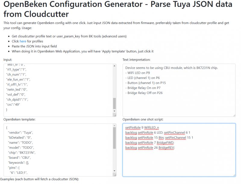
    Thanks for pointing this out - I see that on the Web App the importer did not have bridge relay implemented. Only on the windows app was it entered. I have corrected it:
    Screenshot of the OpenBeken Configuration Generator tool for generating configuration from JSON. .
    Helpful post? Buy me a coffee.
  • ADVERTISEMENT
  • #19 21454550
    abaku
    Level 11  
    EARU EAWCPT-J
    In this version (delivery 02.2025), the location of the LED POWER and LED WIFI is changed https://obrazki.elektroda.pl/7131103900_1740038535.jpg

    working template:
    Code: JSON
    Log in, to see the code
    .

    Notes:
    note to
    "6": "LED _n ;1" - after extraction from tuya the template returns "6": "LED;1"
    flag 41 was active - problem with button not working :-)
    calibration required
    despite calibration the measurement readings float a little
    "flags": "2622468" - above flags 31 are not represented in such a record
  • #20 21454558
    p.kaczmarek2
    Moderator Smart Home
    Thanks for the template, but if you can put it in a syntax json tag.

    Is everything working now? How about the power consumption?

    As for the LED, it's at your discretion - some want it to light up when the relay is open and others when it's closed.
    Helpful post? Buy me a coffee.
  • #21 21454587
    abaku
    Level 11  
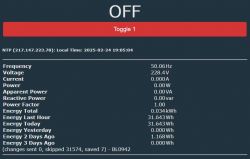
    I'm not sure if the measurement is correct, look at what it indicates when the switch is OFF and when it is ON - there is a current measurement but no active power reading and strangely enough there is a reactive power measurement

    data without load


    Screenshot of electrical measurements with the switch OFF.
    Screenshot displaying electrical energy measurement data, including frequency, voltage, current, apparent and reactive power, and energy consumption. .

    under load looks quite likely

    of curiosities, with the relay off, I can see about 9V on the meter
  • #22 21454603
    p.kaczmarek2
    Moderator Smart Home
    and if you load it with a classic 60W bulb what does it show?
    Helpful post? Buy me a coffee.
  • #23 21454637
    abaku
    Level 11  
    it's not so easy to still have a 60W tungsten bulb :-)
    but I have a 40W Sawtooth


    Screenshot showing energy consumption monitoring with various values such as voltage and power. .

Topic summary

The discussion centers on the teardown, firmware flashing, configuration, and troubleshooting of the EARU EAWCPT-J 35mm DIN Rail WiFi Smart Switch relay with energy metering, controlled via the Tuya app and based on the BK7231N chip. The device requires drilling rivets to open and reassembly solutions include using M1.5 or M3 screws for structural integrity. Firmware flashing methods include a Python script approach when GUI tools fail. Users report hardware revisions with the CBU module relocated to the front, causing pinout changes and a constant-on red WiFi LED due to a wiring error. Configuration challenges involve correct pin assignments for bistable relay control using "BridgeFWD" and "BridgeREV" roles to avoid continuous coil power and overheating. Button functionality issues arise from incorrect pin mapping, resolved by extracting the Tuya configuration to identify the actual button pin. Power consumption anomalies are noted, with reported device heating up to >60°C and power readings from the web interface inconsistent with external meter measurements. Calibration commands (VoltageSet, CurrentSet, PowerSet) and power-saving settings are recommended to optimize performance. Updated JSON configuration templates with corrected pin roles and commands are shared to restore full functionality, including LED behavior and relay control. Users emphasize the importance of verifying hardware revisions, proper pin mapping, and calibration to ensure safe, efficient operation of the EAWCPT-J relay module.
Summary generated by the language model.
ADVERTISEMENT