Arduino R4 WiFi and Joystick shield - your own wireless controller on WiFi
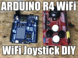
I will show here how we can make our own wireless gamepad based on Arduino R4 WiFi and Joystick shield. Our controller will connect to our WiFi network and send pressed key data to our server via UDP connectionless protocol, which will provide us with fast response to pressed keys.
We will basically only need the title Arduino R4 WiFi and the title joystick shield, to be bought for about a dozen zlotys:

Here it should be noted that this shield offers two types of control:
- the joystick itself allows analog control, by this I mean that the value read from its potentiometers faithfully reflects the bias of the knob
- the buttons, as buttons do, give us only boolean information, true or false, pressed or not
The joystick's analog control capability allows us to be more precise in moving whatever we happen to be controlling.
The joystick shield fits on the Arduino R4, as it has the same form factor as the previous Uno R3:
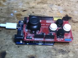
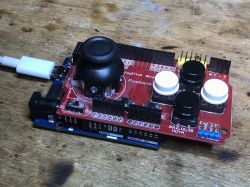
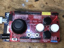
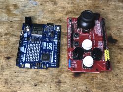 Running the joystick shield Let's start with just running the shield. Fortunately, as is common in the Arduino environment, we already have a sketch ready for this.
 The JoystickShield class cleverly hides the button and ADC readout behind nice, well-described functions.
Code: C / C++
Upload, test:
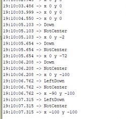
Everything works, and we have swings in the range of -100 to 100, so these are no ordinary buttons - that's what we wanted, this allows to control the given device in a precise way.
We pack in our own structure
This collected data needs to be passed on somehow. For this purpose, it is useful to pack it into a structure. Buttons can be in one field of integer type (or even can fit in a byte) as individual bits. This is how we save space. On the other hand, the pivot must already be as an integer with a sign. In addition, I added myself a packet ID, which is essentially its next index, incremented with each data send.
Code: C / C++
This is how the structure is filled in. The global variable counts down the next packets.
Code: C / C++
You still need to fill in the buttons. To do this, I added an enumeration specifying which bit index is responsible for which button:
Code: C / C++
Then you need to light up the corresponding bit when a given button is pressed. To convert the index of a bit into a mask you need to use a bit shift, and to light up that bit, you use OR.
Code: C / C++
. We send the data over UDP Now we need to send our structure over the network. I decided to use the connectionless UDP protocol. He, admittedly, may lose packets, but at least it will transmit them quickly. I figured this was more important than the reliability of the connection that TCP offers.
So let's review the demo from the Arduino R4 itself, the UDP client of the NTP service:
Code: C / C++
Basically, we need to use the send shown above:
Code: C / C++
Please note that we are sending data to a specific IP address and port. The server must be listening on that IP address and port.
Modifying the above code is very simple. We simply remove the sending according to the NTP protocol and instead send our structure. Done.
Receive data on computer Now we still need to receive the sent data. We will use a UDP server for this. A UDP server can be very easily created in C# using the UdpClient class.
It is important to listen on the same port to which we send data.
Then we can receive packets in a loop and process them using BinaryReader. We don't have to worry about fragmentation here, such small packets are not split, they fit entirely in one frame:
Code: C / C++
We fire up both programs, both joystick and server.... We make sure they are on the same WiFi network and.... success:
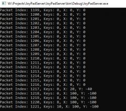
Our program correctly receives data from the controller.
Summary A simple and pleasant project. Already in principle you can control something on a PC.
Analogously you can put a UDP server on a second Arduino, ESP or whatever and there receive packets with user input.
Also you could develop my application written in C# so that it sends Windows key presses or there move the mouse, then our Arduino gamepad would even allow us to control our PC.
The possibilities are very large.
Do you see any use for such a DIY?
Finally, let me also remind you of my earlier gamepad that I implemented on a PIC:
USB/HID gamepad on PIC18F45K50 (with additional mouse mode and CDC)
PS: If you don't care about the fast response of the controlled device, but you do care about every packet reaching its destination, you should rewrite the example to use reliable, connection-based TCP. TCP guarantees, sent packets will arrive (unless the connection is completely broken) and resends them if there is a problem, while UDP sends them blindly without checking for reception) .


Comments
Interesting project How about delays? [Read more]
To investigate latency, I would probably want to implement my own "ping" mechanism, i.e., number the sent packets and remember their sending times on the Arduino (at least the last N sent), and in the... [Read more]