logo elektroda
logo elektroda
X
logo elektroda
Dostępna jest polska wersja

Czy wolisz polską wersję strony elektroda?

Nie, dziękuję Przekieruj mnie tam

Arduino R4 WiFi and Joystick shield - your own wireless controller on WiFi

p.kaczmarek2 3093 2

TL;DR

  • Builds a wireless gamepad from an Arduino R4 WiFi and a joystick shield, sending joystick and button input to a PC over WiFi.
  • Packages button states into bitfields plus a signed joystick axis and packet ID, then streams the structure via UDP to a listening server.
  • The joystick readout spans -100 to 100, giving analog control instead of simple on/off button input.
  • Running both programs on the same WiFi network successfully delivers controller packets, but UDP can lose packets, so TCP is better for guaranteed delivery.
Summary generated by AI based on the discussion content.
ADVERTISEMENT
Treść została przetłumaczona polish » english Zobacz oryginalną wersję tematu
📢 Listen (AI):
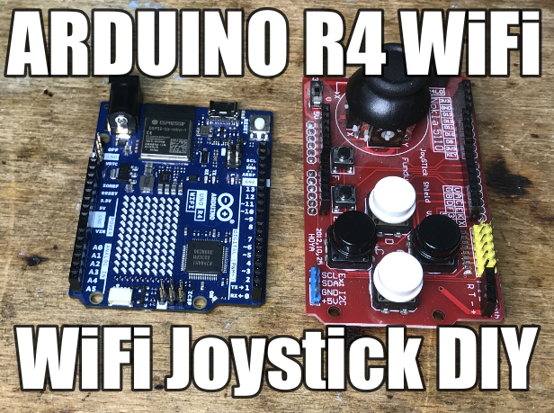
  • Arduino R4 WiFi and joystick shield on a wooden background
    I will show here how we can make our own wireless gamepad based on Arduino R4 WiFi and Joystick shield. Our controller will connect to our WiFi network and send pressed key data to our server via UDP connectionless protocol, which will provide us with fast response to pressed keys.

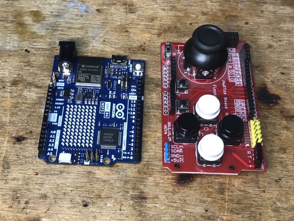
    We will basically only need the title Arduino R4 WiFi and the title joystick shield, to be bought for about a dozen zlotys:
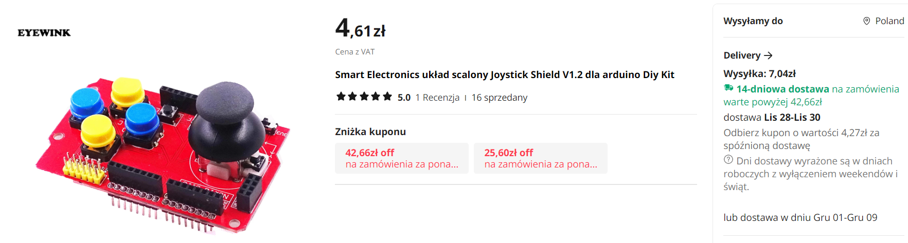
    Joystick Shield V1.2 for Arduino with four buttons on a red board.
    Here it should be noted that this shield offers two types of control:
    - the joystick itself allows analog control, by this I mean that the value read from its potentiometers faithfully reflects the bias of the knob
    - the buttons, as buttons do, give us only boolean information, true or false, pressed or not
    The joystick's analog control capability allows us to be more precise in moving whatever we happen to be controlling.
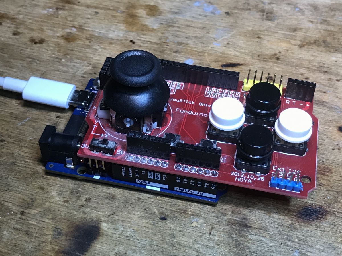
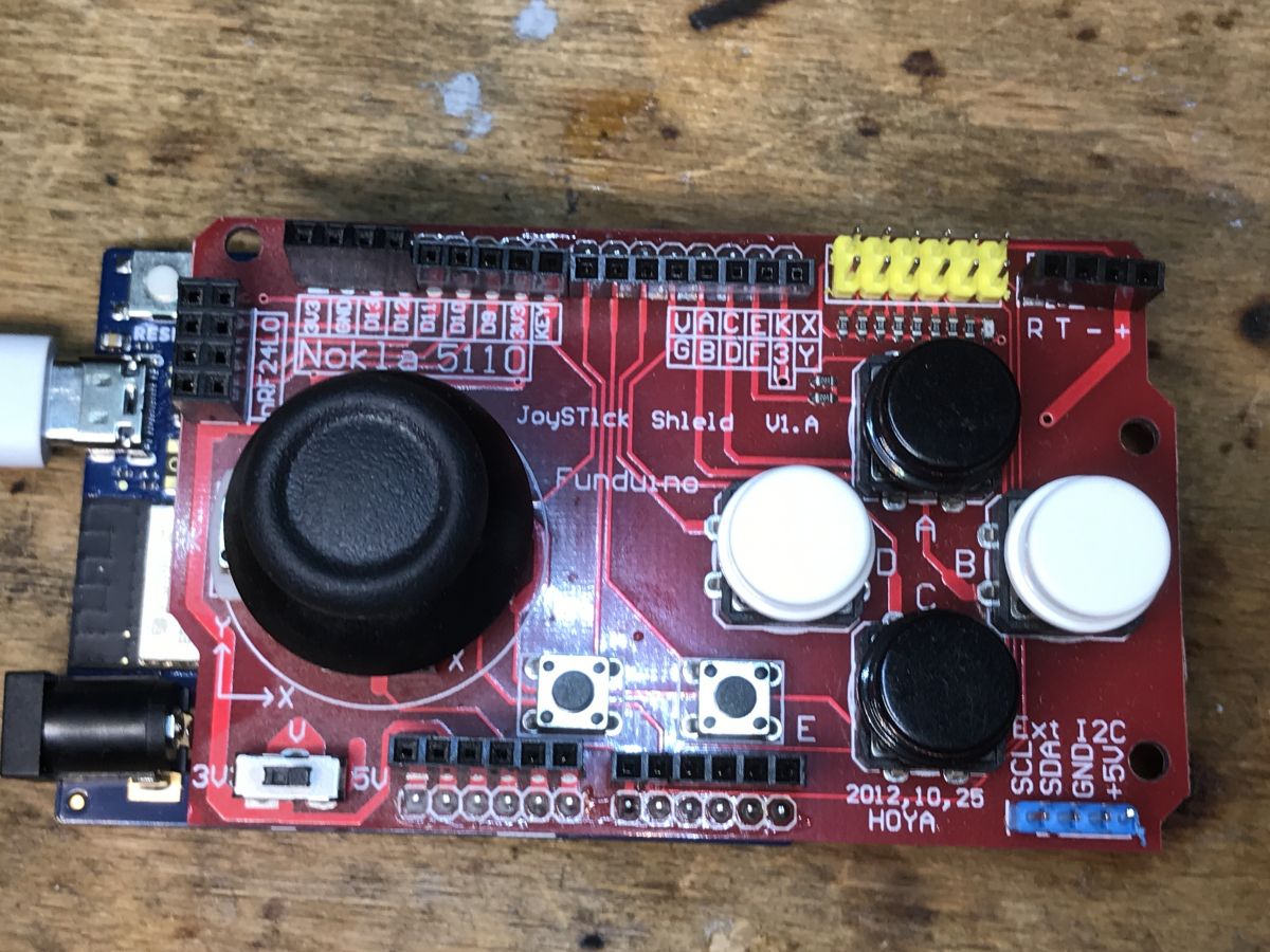
    The joystick shield fits on the Arduino R4, as it has the same form factor as the previous Uno R3:
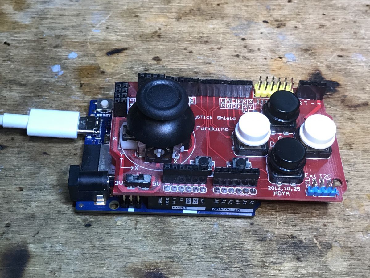
    Joystick Shield module mounted on Arduino R4 WiFi. Joystick shield mounted on an Arduino board with a connected USB cable. Joystick shield on an Arduino board with buttons and control elements Arduino R4 WiFi and Joystick Shield on a wooden desk Running the joystick shield Let's start with just running the shield. Fortunately, as is common in the Arduino environment, we already have a sketch ready for this.
    The JoystickShield class cleverly hides the button and ADC readout behind nice, well-described functions.
    Code: C / C++
    Log in, to see the code

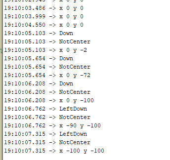
    Upload, test:
    Console monitoring of Arduino joystick data.
    Everything works, and we have swings in the range of -100 to 100, so these are no ordinary buttons - that's what we wanted, this allows to control the given device in a precise way.


    We pack in our own structure
    This collected data needs to be passed on somehow. For this purpose, it is useful to pack it into a structure. Buttons can be in one field of integer type (or even can fit in a byte) as individual bits. This is how we save space. On the other hand, the pivot must already be as an integer with a sign. In addition, I added myself a packet ID, which is essentially its next index, incremented with each data send.
    Code: C / C++
    Log in, to see the code


    This is how the structure is filled in. The global variable counts down the next packets.
    Code: C / C++
    Log in, to see the code


    You still need to fill in the buttons. To do this, I added an enumeration specifying which bit index is responsible for which button:
    Code: C / C++
    Log in, to see the code

    Then you need to light up the corresponding bit when a given button is pressed. To convert the index of a bit into a mask you need to use a bit shift, and to light up that bit, you use OR.
    Code: C / C++
    Log in, to see the code


    . We send the data over UDP Now we need to send our structure over the network. I decided to use the connectionless UDP protocol. He, admittedly, may lose packets, but at least it will transmit them quickly. I figured this was more important than the reliability of the connection that TCP offers.
    So let's review the demo from the Arduino R4 itself, the UDP client of the NTP service:
    Code: C / C++
    Log in, to see the code


    Basically, we need to use the send shown above:
    Code: C / C++
    Log in, to see the code


    Please note that we are sending data to a specific IP address and port. The server must be listening on that IP address and port.
    Modifying the above code is very simple. We simply remove the sending according to the NTP protocol and instead send our structure. Done.

    Receive data on computer Now we still need to receive the sent data. We will use a UDP server for this. A UDP server can be very easily created in C# using the UdpClient class.
    It is important to listen on the same port to which we send data.
    Then we can receive packets in a loop and process them using BinaryReader. We don't have to worry about fragmentation here, such small packets are not split, they fit entirely in one frame:
    Code: C / C++
    Log in, to see the code

    We fire up both programs, both joystick and server.... We make sure they are on the same WiFi network and.... success:
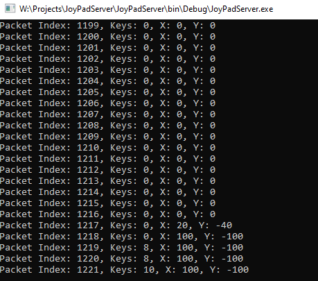
    Console window with a running JoyPad server.
    Our program correctly receives data from the controller.

    Summary A simple and pleasant project. Already in principle you can control something on a PC.
    Analogously you can put a UDP server on a second Arduino, ESP or whatever and there receive packets with user input.
    Also you could develop my application written in C# so that it sends Windows key presses or there move the mouse, then our Arduino gamepad would even allow us to control our PC.
    The possibilities are very large.
    Do you see any use for such a DIY?
    Finally, let me also remind you of my earlier gamepad that I implemented on a PIC:
    USB/HID gamepad on PIC18F45K50 (with additional mouse mode and CDC)
    PS: If you don't care about the fast response of the controlled device, but you do care about every packet reaching its destination, you should rewrite the example to use reliable, connection-based TCP. TCP guarantees, sent packets will arrive (unless the connection is completely broken) and resends them if there is a problem, while UDP sends them blindly without checking for reception) .

    Cool? Ranking DIY
    Helpful post? Buy me a coffee.

    About Author
    p.kaczmarek2
    Moderator Smart Home
    Offline 
    p.kaczmarek2 wrote 14699 posts with rating 12743, helped 656 times. Been with us since 2014 year.
  • ADVERTISEMENT
  • #2 20852891
    LA72
    Level 41  
    Posts: 6594
    Help: 648
    Rate: 1655
    Interesting project
    How about delays?
  • Ping-based RTT measurement for WiFi latency

    #3 20853049
    p.kaczmarek2
    Moderator Smart Home
    Posts: 14699
    Help: 656
    Rate: 12743
    To investigate latency, I would probably want to implement my own "ping" mechanism, i.e., number the sent packets and remember their sending times on the Arduino (at least the last N sent), and in the client in C# send back some simple ACK also with the packet number. Then on the Arduino, at the time of receiving the ack, one could find the sending time of a given packet and subtract it from the current time to get the RTT (Round Trip Time, round trip communication time).
    It would then be possible to give the display of this RTT in general to the functionality of the program, just as some other services display.
    As for the latency values themselves, it would probably depend a lot, as is usually the case, as for WiFi itself...
    Another thing is that for the greatest responsiveness you would have to optimize the logic of sending packets, not always send them every fixed time, but send them as soon as possible as there is a change, and every fixed time if there is no change.
    For sure, the presented demo gives a lot of room for improvement and development.
    Helpful post? Buy me a coffee.
📢 Listen (AI):

FAQ

TL;DR: This DIY WiFi controller uses 1 Arduino UNO R4 WiFi, 1 joystick shield, and joystick values from about -100 to 100. "UDP gives fast response," so it suits makers who want a low-cost wireless gamepad that sends button and stick data to a PC over WiFi. [#20852158]

Why it matters: It shows a simple path from raw joystick input to real network control, so you can prototype a custom wireless gamepad without designing your own radio protocol.

Option Main benefit Main drawback Best use in this project
UDP Fast response, simple packets Packets can be lost Live controller input
TCP Reliable delivery, retransmission More overhead and delay Commands where every packet must arrive

Key insight: The thread’s core idea is to read analog stick movement and button states, pack them into one small struct, and send that struct directly over WiFi. That keeps both the Arduino code and the PC receiver easy to extend.

Quick Facts

  • The joystick shield fits the Arduino UNO R4 WiFi because it keeps the UNO R3 form factor, so the shield can stack directly on the board. [#20852158]
  • The analog stick reports swings of about -100 to 100, which gives proportional control instead of simple pressed/not-pressed input. [#20852158]
  • The sample packet uses 4 signed integers: packetID, x, y, and buttons, which makes the payload compact and easy to decode on a PC. [#20852158]
  • The example PC receiver listens with UdpClient on port 12345, and the Arduino must send to that same port on the target IP address. [#20852158]
  • The NTP demo shown in the thread uses a 48-byte NTP buffer and local UDP port 2390, then gets repurposed by replacing the time request with a custom joystick payload. [#20852158]

How do I build a WiFi game controller with an Arduino R4 WiFi and a Joystick Shield?

You build it by stacking the joystick shield onto the Arduino UNO R4 WiFi, reading stick and button states, then sending them over WiFi as UDP packets. 1. Mount the shield and run the JoystickShield example to confirm inputs work. 2. Store x, y, buttons, and a packet counter in one struct. 3. Send that struct to a PC IP and UDP port, then decode it with a small C# server. The thread says the shield costs about a dozen złoty and the stick gives analog values near -100 to 100. [#20852158]

What pins and functions does the JoystickShield library use to read the analog stick and buttons on Arduino R4 WiFi?

The example uses joystick analog pins 0 and 1 and button pins 8, 2, 3, 4, 5, 7, and 6. The library reads states through functions such as isUp(), isRight(), isJoystickButton(), isEButton(), isFButton(), xAmplitude(), yAmplitude(), and processEvents(). The sketch also calls calibrateJoystick() during setup. If your shield uses different wiring, you must change setJoystickPins() and setButtonPins() to match. [#20852158]

How can I pack joystick position and button states into a compact C struct before sending them over WiFi?

Use one small C struct with four integers and fill it before each send. The thread uses struct JoyData { int packetID; int x; int y; int buttons; };. That layout keeps stick position in signed fields and packs all button states into one integer. Increment packetID for each packet so the receiver can track order or detect loss. The shown code fills x, y, and buttons immediately before transmission. [#20852158]

What's the correct way to encode multiple joystick buttons into one integer using bit masks and enums in Arduino code?

Define one enum value per button, then set bits in a single integer with left shifts and OR operations. The thread shows an enum with entries for joystick, E, F, right, left, up, and down. For example, when a button is pressed, set data.buttons |= (1 << BTN_E);. This approach stores up to several on/off states in one field instead of using many separate variables. [#20852158]

How do I send joystick data from Arduino R4 WiFi over UDP to a specific IP address and port?

Open a UDP packet to the target IP and port, write the struct bytes, and close the packet. The thread reduces the send logic to three calls: Udp.beginPacket(address, port);, Udp.write(&data, sizeof(JoyData));, and Udp.endPacket();. The destination must be a specific IP address and the receiver must listen on that same port. In the example ecosystem, the PC listener uses port 12345. [#20852158]

How can I write a simple C# UDP server with UdpClient to receive Arduino joystick packets on a PC?

Create a UdpClient on the chosen port, receive datagrams in a loop, and decode four 32-bit integers with BinaryReader. The thread’s sample server listens on port 12345, then reads packetIndex, x, y, and keys from a MemoryStream. It prints each packet to the console, which is enough to verify live communication. This works because the packet is small and the sender and receiver use the same field order. [#20852158]

Why does the joystick shield on Arduino R4 WiFi return analog values from about -100 to 100 instead of just pressed or not pressed?

It returns analog values because the joystick uses potentiometers, not simple digital switches. The thread states that the shield provides two control types: the stick gives proportional analog output, while the buttons give boolean pressed or not pressed data. That is why xAmplitude() and yAmplitude() can show swings near -100 to 100 and allow finer movement control than ordinary buttons. [#20852158]

What is RTT in WiFi communication, and how would I measure controller latency between Arduino and a C# client?

RTT is the round-trip communication time between send and acknowledgment. "RTT" is a network timing metric that measures how long one packet takes to go from sender to receiver and back again, including transmission, processing, and return acknowledgment delay. To measure it here, number outgoing packets, store recent send times on the Arduino, and make the C# client send back a small ACK with the same packet number. When the Arduino receives that ACK, subtract the saved send time from the current time. [#20853049]

UDP vs TCP for a DIY wireless gamepad on Arduino R4 WiFi — which is better for fast response and which is better for reliable delivery?

UDP is better for fast response, while TCP is better when every packet must arrive. The thread explicitly chooses UDP because it is connectionless and faster, even though it can lose packets. It also states that TCP resends lost data and guarantees delivery unless the connection fully breaks. For live stick motion, lost old packets matter less than low delay, so UDP fits this gamepad design. [#20852158]

What is the NTP UDP client example on Arduino R4 WiFi, and how can it be adapted to send custom joystick packets instead of time requests?

It is an Arduino WiFi UDP demo that normally sends a 48-byte NTP request to a time server and waits for a reply. To adapt it, keep the WiFi connection and WiFiUDP setup, but remove the NTP-specific packet buffer logic. Then replace Udp.write(packetBuffer, NTP_PACKET_SIZE); with Udp.write(&data, sizeof(JoyData)); and send to your PC’s IP and chosen port instead of port 123. [#20852158]

How should I optimize packet sending for the lowest delay — send on every fixed interval or only when joystick state changes?

Send immediately when the joystick state changes, and send periodically only as a keepalive when nothing changes. The thread says the best responsiveness comes from not always sending at a fixed interval. That means event-driven sends should handle active input, while a slower fixed timer can maintain presence during idle periods. This reduces unnecessary traffic and cuts control lag during rapid movement. [#20853049]

What kinds of delays should I expect when using a WiFi-based Arduino joystick controller, and what affects the latency most?

Expect variable delay rather than one fixed number, because WiFi conditions dominate latency. The thread does not give measured milliseconds, but it says latency will depend heavily on the WiFi link itself and recommends measuring RTT with packet numbers and ACKs. Send strategy also matters: fixed-interval sending adds delay, while sending on change improves responsiveness. In practice, network quality and firmware logic affect delay more than the joystick hardware. [#20853049]

Which port numbers, IP settings, and network conditions need to match for an Arduino UDP client and a C# UDP server to communicate properly?

The Arduino must send to the correct destination IP and the exact UDP port that the PC server is listening on. The thread states this directly and demonstrates a C# listener on port 12345. Both devices must also be on the same WiFi network for the shown setup. If the IP address is wrong, the port differs, or the boards connect to different networks, the packets will not reach the receiver. [#20852158]

What common mistakes can stop a Joystick Shield from working correctly on an Arduino R4 WiFi, even if it fits the Uno R3 form factor?

Wrong pin mapping, skipped calibration, and mismatched field handling can break the setup even when the shield physically fits. The thread notes that the shield fits because the R4 keeps the UNO R3 form factor, but the software still depends on correct joystick and button pin assignments. The sample also contains a likely typo where data.y is filled from xAmplitude() instead of yAmplitude(), which would corrupt Y-axis data. [#20852158]

How could I extend this Arduino WiFi gamepad project to control Windows keyboard presses or mouse movement from the received C# data?

Use the received x, y, and button bits in the C# app to trigger keyboard events or move the mouse. The thread explicitly suggests extending the C# receiver so it sends Windows key presses or controls the cursor, turning the Arduino gamepad into a PC input device. Because the packet already includes analog axes and packed buttons, you only need to map those fields to desktop actions inside the PC program. [#20852158]
Summary generated by AI based on the discussion content.
ADVERTISEMENT