FAQ
TL;DR: For owners flashing 7-11 Beca BAC-002/BHT-002 thermostats, "start with one device" is the safest rule: make a full 2MB backup, isolate the TuyaMCU, and use a stable 3.3V supply because a USB-UART adapter alone may fail during flashing. This FAQ shows how to flash OpenBK, recover from read errors, and handle relay-state or sensor mods without damaging the board. [#20897615]
Why it matters: These thermostats look simple, but one wrong power or UART setup can leave a flashed board with no hotspot, no web UI, and unreliable backups.
| Option |
Main advantage |
Main risk |
Best use |
| BK7231GUIFlashTool over UART |
Full backup and direct OpenBK flashing |
You may need to isolate the MCU and provide external 3.3V |
Repairable, repeatable bench work |
| Tuya Cloudcutter |
No UART soldering on supported units |
No guaranteed full dump path in this thread |
Faster conversion of another compatible unit |
Key insight: The biggest failure point was not OpenBK itself. It was powering and wiring the Wi-Fi module correctly while temporarily separating it from the thermostat MCU.
Quick Facts
- The BAC-002 dump discussed in the thread uses a 2MB flash backup workflow before writing
OpenBK7231N_QIO_1.17.406.bin, so backup comes before experimentation. [#20896307]
- The thermostat’s Wi-Fi module was flashed through RX1, TX1, 3.3V, and GND, with users specifically citing pins 8 and 9 for power and ground on the module footprint. [#20909148]
- Power datapoints identified in the thread include dpID 1 for power, 2 for target temperature, 3 for current temperature, 102 for HVAC/operation mode, and 103 for fan speed. [#21392023]
- One user reported successfully flashing 11 units with a simple pogo-pin setup, but the thread still warns that pogo pins alone do not remove the need to isolate the MCU path. [#21391966]
- On newer equivalent boards with a 3.3V MCU, relay-state sensing is easier because there is no need to reduce voltage for the CB3S pin used to derive relay information. [#21398125]
How do I flash a Beca BAC-002 or BHT-002 thermostat with OpenBK on a WB3S or CB3S module without damaging the board?
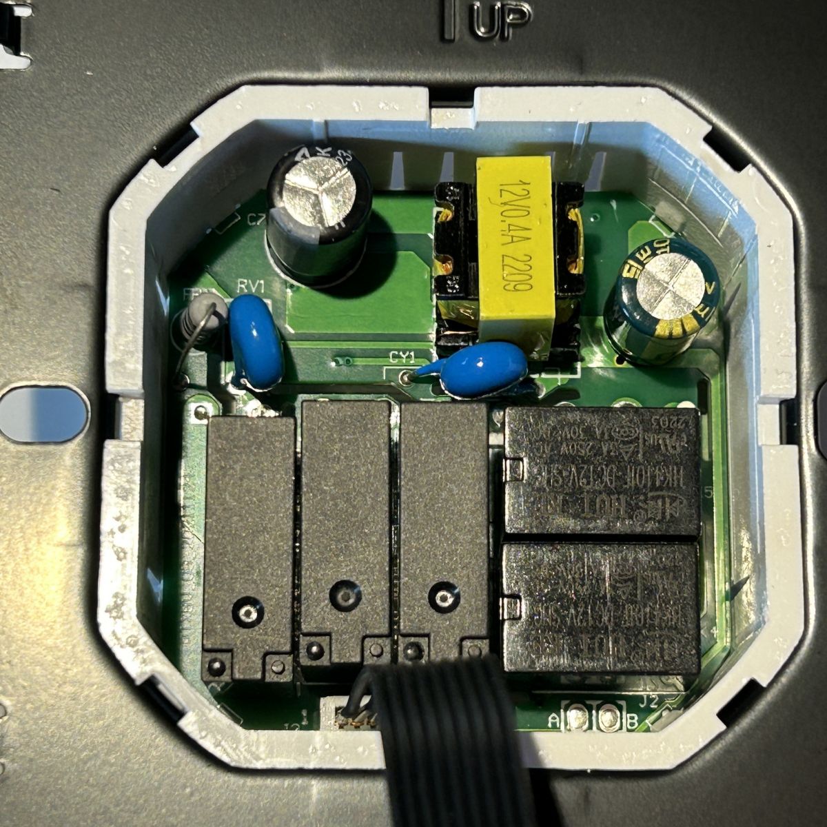
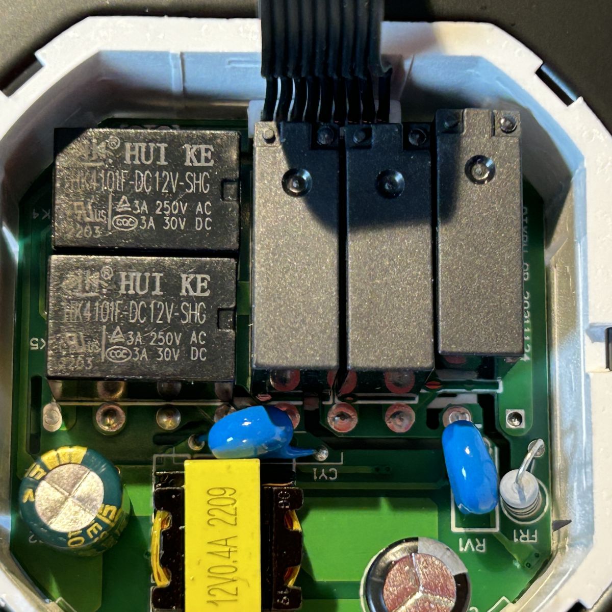
Flash it by backing up first, isolating the MCU, and using a stable 3.3V supply. 1. Remove the two 0Ω links or other UART path jumpers that connect the Wi-Fi module to the thermostat MCU. 2. Read a full 2MB dump before writing OpenBK. 3. Power the module externally at 3.3V and connect RX1/TX1 only after confirming the UART wiring. The thread’s expert advice was: "Let’s start with flashing and configuring one device." That reduces risk before repeating the process on 7 or more boards.
[#20897615]
What is TuyaMCU, and how does it change the way a Beca thermostat is flashed and configured in OpenBK?
TuyaMCU changes the job because the thermostat logic runs on a separate MCU, not on the Wi-Fi chip alone.
"TuyaMCU" is a serial control architecture that lets a main thermostat MCU exchange datapoints with the Wi-Fi module, which means flashing OpenBK does not automatically expose native GPIO behavior or standard OpenBK config pages. That is why the thread says OBK config will not help much on this device class, and why datapoint mapping matters more than raw pin roles after flashing.
[#20908698]
Why does a BK7231 flash backup fail with errors like "CheckRespond_FlashRead4K: ERROR" after an apparently successful first read?
That error usually means the module is no longer being powered or isolated correctly for a stable second read. In the thread, the first backup succeeded, but later reads failed after rewiring, desoldering, and reconnecting the thermostat. The strongest root cause discussed was inadequate current from the USB-UART setup, plus possible UART contention from the main MCU if isolation was not maintained. A CRC error during reflashing pointed to the same class of instability: power or connection faults, not a proven dead BK7231 module.
[#20909568]
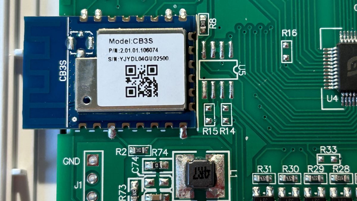
What's the correct way to power a CB3S or WB3S thermostat during flashing if a USB-UART adapter cannot supply enough current?
Power the Wi-Fi module from a reliable external 3.3V source, not from the USB-UART adapter alone. The thread states that this adapter will not provide enough current for flashing. Set the adapter’s logic level to 3.3V with its jumper, then power the thermostat board separately. An alternative shown in the thread is feeding 5V from USB into the board’s AMS1117-3.3V regulator input, if that LDO is present, to obtain a stable 3.3V rail for the CB3S or WB3S module.
[#20909568]
How can I make a full 2MB flash backup of a Beca BAC-002 thermostat before installing OpenBK?
Make the backup over UART before writing any firmware. 1. Disconnect or cut the MCU-to-Wi-Fi UART path temporarily. 2. Wire GND, 3.3V, RX, and TX to the Wi-Fi module and keep power stable. 3. Use BK7231GUIFlashTool to read the full 2MB flash and save the dump before flashing OpenBK. The thread explicitly recommends starting with a 2MB backup and points to BK7231GUIFlashTool as the resource for doing it.
[#20896307]
Why might an OpenBK-flashed thermostat stop showing its Wi-Fi hotspot or web interface after rebooting?
It may lose the hotspot because the module is not booting correctly after flash, not because OpenBK always failed. In the thread, the thermostat worked after the first flash, then showed no hotspot after power-down and rewiring. The likely causes were unstable 3.3V power, bad UART connections, or a flashing session corrupted by low current, later confirmed by read failures and a CRC error. On this TuyaMCU thermostat, the absence of the OpenBK page does not prove the board is dead, but it does signal a boot or power problem.
[#20909148]
Which is the better approach for these thermostats: flashing with BK7231GUIFlashTool over UART or using Tuya Cloudcutter?
UART flashing is the better documented path in this thread if you want a full backup and controlled recovery. BK7231GUIFlashTool was recommended first because it supports the 2MB dump and direct OpenBK flashing. Tuya Cloudcutter did work on another thermostat in the same family, but the thread presents it as an additional success, not the main step-by-step method. Use UART when you need repeatable bench workflow and a saved original dump; use Cloudcutter when a supported unit flashes cleanly and you accept a less hardware-centric path.
[#20915193]
What is a dpID in Tuya devices, and how do I identify the BAC-002 thermostat datapoints for power, target temperature, current temperature, mode, and fan speed?
A dpID is the thermostat’s named control or telemetry field on the Tuya serial link.
"dpID" is a Tuya datapoint identifier that maps one function, such as power or temperature, to a numeric ID exchanged between the MCU, app, and Wi-Fi module, usually with a type like bool, value, enum, or raw. In this BAC-002 thread, dpID 1 is power, 2 is target temperature, 3 is current temperature, 4 is schedule/manual mode, 102 is operation mode, and 103 is fan speed.
[#21392023]
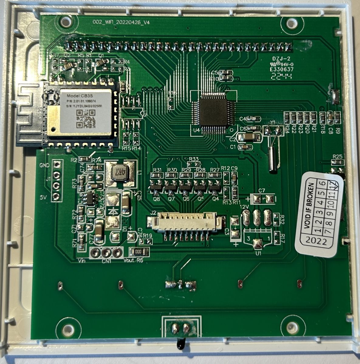
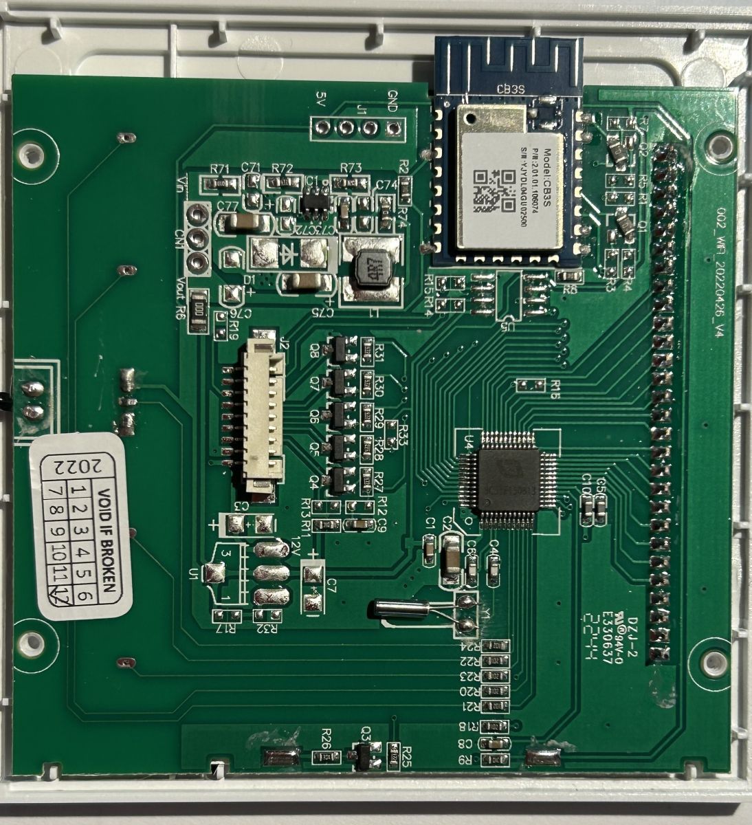
How do I temporarily isolate the Wi-Fi module from the main MCU when flashing a Tuya thermostat, and which resistors or jumpers usually need to be removed?
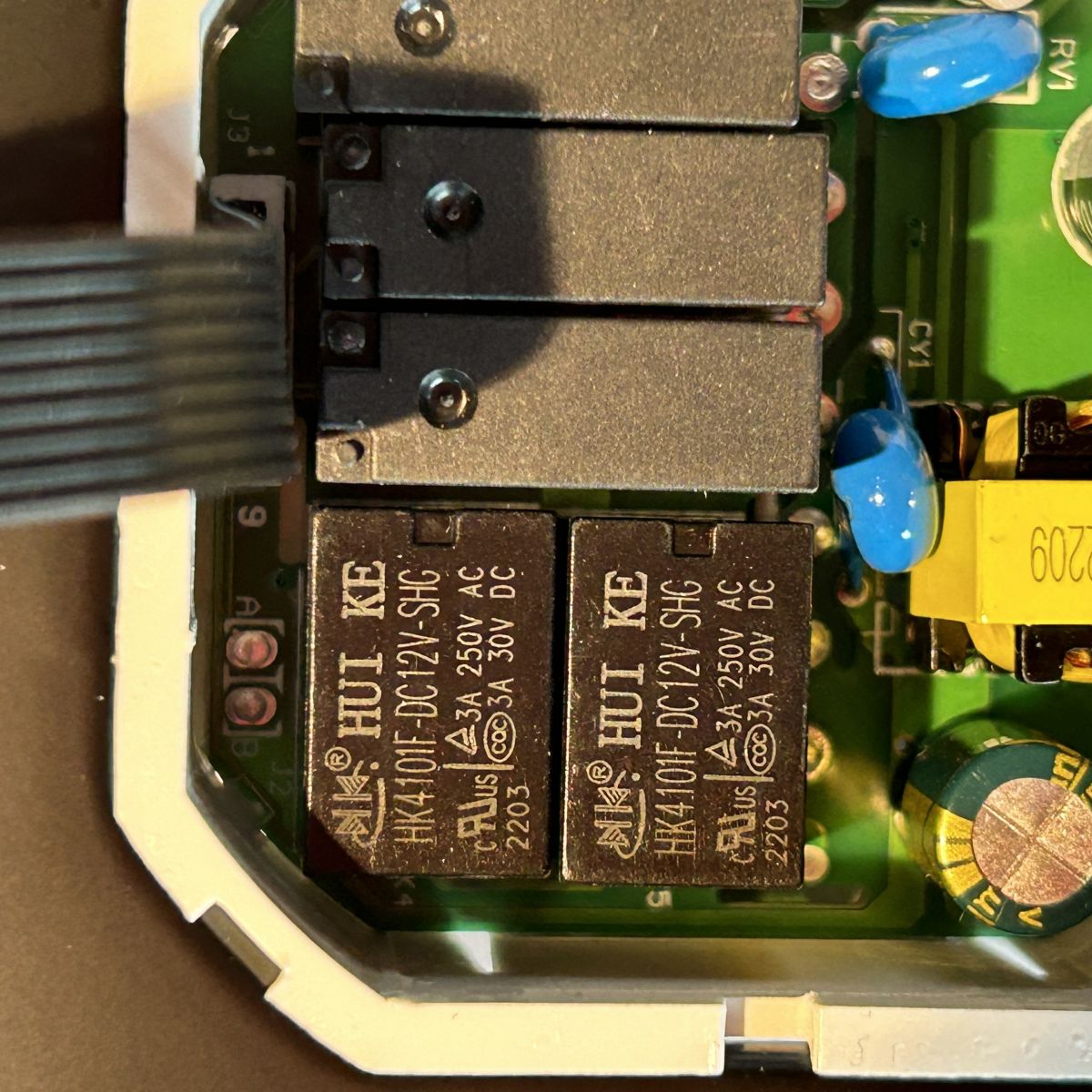
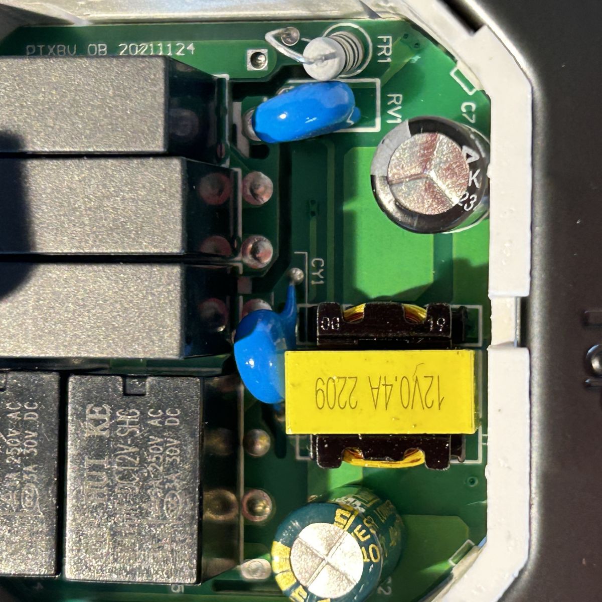
Temporarily isolate it by removing the UART link components between the main MCU and the Wi-Fi module. The user in the thread desoldered two resistors that handled MCU communication, and a later post clarifies those parts are simply 0Ω jumpers. Once removed, the Wi-Fi module can be accessed directly over RX and TX for backup or flashing. Restore them after testing if you need the original serial link again. On newer equivalent boards, that same 3.3V MCU arrangement also simplifies relay-state pickup.
[#21398125]
Why would TX2 show no serial log output on a flashed thermostat, and what wiring or baud-rate mistakes should I check first?
No TX2 log usually means the board is powered wrongly or the serial pins are not the ones actually active in your setup. Check three things first: 1. The module has a stable 3.3V supply. 2. TX and RX are crossed correctly on the right UART pads. 3. The MCU is not still loading or blocking the serial line. In the thread, the expert response did not blame PuTTY first; it asked how the device was powered and requested a wiring photo, which points to hardware setup as the main failure source.
[#20909105]
How can I read the relay on/off state from a Beca thermostat after flashing OpenBK, including the common hardware mod mentioned in the thread?
Read the relay state by tapping the relay-drive signal with the hardware mod already referenced in the thread. The opening post links to an earlier mod specifically intended to expose relay on/off status, and a later post adds that newer equivalent boards use a 3.3V MCU, making the pickup easier because you do not need to reduce the voltage for the CB3S input. On older layouts, the same signal may need level care before it reaches the Wi-Fi module GPIO.
[#21398125]
What is the difference between WB3S and CB3S in Beca thermostats, and how does that affect flashing and relay-state sensing?
The thread treats WB3S as the older module and CB3S as the newer one, but the flashing principles stay the same: backup first, isolate the MCU, and use stable 3.3V power. The practical relay-state difference appears on newer equivalent boards with a 3.3V MCU, where deriving the relay signal is easier and no level reduction is needed for the CB3S pin. So the important difference in this thread is less about firmware steps and more about how safely you can sense board-level signals.
[#21398125]
How can I add an external temperature or humidity sensor to a Beca BAC-002/BHT-002 thermostat if the original sensor is connected to the MCU instead of the Wi-Fi module?
You cannot add it cleanly through OpenBK alone if the sensor is wired to the thermostat MCU. The thread states the main limitation clearly: the onboard sensor is connected to the MCU, not to the Wi-Fi module, so the flashed Wi-Fi side does not control that reading path. Your practical options are hardware rework on the original sensor connection, using compensation logic elsewhere, or building a Home Assistant-side control workaround. The thread does not confirm any direct humidity-sensor add-on path to the BAC-002/BHT-002 MCU.
[#21391977]
What are the practical options for compensating for bad temperature readings when the thermostat is mounted near a fan coil, such as calibration dpIDs, rewiring the onboard sensor, or handling it in Home Assistant?
Use calibration if the thermostat exposes it; otherwise relocate the sensor electrically or compensate in Home Assistant. In this thread, no calibration dpID was found in the extracted BAC-002 datapoint list, even though the manual mentioned calibration. The fallback advice was to extend or relocate the existing sensor with wires and test whether added resistance or interference remains acceptable on the bench. A third option raised by the user was a custom Home Assistant climate entity that uses another sensor instead of the thermostat’s built-in reading.
[#21392046]
What's the best pogo-pin setup for flashing multiple Beca thermostats reliably, and when do I still need to solder wires instead?
A pogo-pin jig is the best scaling method, but only after one thermostat has been fully proven. One user planned a 3D-printed pogo-pin adapter for 7 devices, and another later reported flashing 11 units with a simple pogo-pin setup. Even so, the thread shows pogo pins do not solve everything. You may still need to remove the MCU jumpers, hold alignment firmly, or solder wires when pogo contact is unstable or when you need guaranteed UART access during backup and recovery.
[#21391966]
AI summary based on the discussion. May contain errors.






Comments
Hello, this should be easily doable, we actually already had a similiar topic here: https://www.elektroda.com/rtvforum/topic4003974.html Have you seen that? The topic above even includes the relay... [Read more]
First of all, thank you for all your effort on this project and thank you for your reply. I'm aware of the other thread, I've already studied it. I will try to backup the device and to flash the new firmware.... [Read more]
Let's start with flashing and configuring one device, we need to test the whole setup first. I am not sure if just having pogo pins solves all problems, because you still may need to cut the connection... [Read more]
Sorry for late reply, very busy week. Yesterday i had some spare time. I've desoldered two resistor which communicate with MCU. No luck with pogo pins, so i've soldered four wires to wifi chip. At... [Read more]
OBK config will not help for TuyaMCU device. What does the TX2 log output say? [Read more]
Well, i don't see any output connecting on tx2. I'm using putty in serial mode to see if there is an output, am i doing wrong? i'm using this as usb-uart adapter. Hope it is good. p.s. sorry for... [Read more]
how do you power your device, can you make a photo of connections?" [Read more]
https://obrazki.elektroda.pl/2431763200_1705246683_thumb.jpg This is how i am powering the device. Now i'm trying to use a usb-esp01 adapter, to see if it helps. Now the led screen of the thermostat... [Read more]
You are using your USB to UART converter incorrectly. You should use jumper to connect 3.3V to VCC on USB to UART converter to select 3.3V voltage levels and power the device externally from a reliable... [Read more]
Hi, sorry for late reply. I haven't been able to flash new firmware. i will try to do it in a few days. During the first attempt, I have been able to backup the original flash. if you want it i can... [Read more]
Hi all, i want to "hi-jack" this post to post my first response on the forum. I just finished flashing 11 of these units with a simple pogo-pin set-up so if anyone needs some easy solution to flash these... [Read more]
Some Tuya thermostats support connecting external sensor out of the box, is it the case here? Do you have a manual? If not, then we will have to try more DIY approach, but there is one problem - sensor... [Read more]
yeah this one does not support an external sensor out of the box so i'll probably have to go for the DIY approach. Please see the manual attached. I'm also posting the firmware backup for the other user... [Read more]
Do you have it still paired with App? Does it have a calibration option there? Added after 43 : EDIT: There is calibration mentioned in manual. [Read more]
No i never paired it with the app to begin with unfortuantely, but there is a menu setting. It's also visible in the manual [Read more]
Hm ok, we have a backup so we also can do dpID extraction, maybe @divadiow can also help. There are also some dpIDs in the first post. [Read more]
柏益加温控器(空调) { "gw_bi": { "uuid": "7066c8c661a88a2e", "psk_key": "cw1ygXBCnRDriFY12daQJPgnSBiuBfu6sincM", "auth_key": "c2kQykz6kTORTKuRSh6rgeHLpZcycGY2", "ap_ssid":... [Read more]
No calibration? [Read more]
So what are you saying is to try to use the temperature compensation dpID to "mimic" an external sensor by modifying what the internal sensor read? I've not seen this value being exposed by the tuya mcu. See... [Read more]