Running the HD2015 display/button controller after reverse engineering, comparison with TM1650
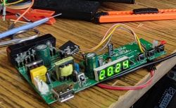 In the previous topic I managed to capture the HD2015 communication using a Salae logic state analyser, bought for £40. Here I will continue the work and try to map this communication in my code written in C, for variety I will use the LN882H platform here. By the way in practice I will compare the handling of this controller with controllers such as TM1637, TM1638, etc.
This topic is a continuation of the following thread:
Salae 24MHz logic state analyser for 10$ - analysis of an unknown LED display protocol
This time will be a bit shorter, I will simply verify here that I have deciphered the protocol correctly...
There was chaos at first
There's not much to comment on here, but my fun is to remove what is unnecessary from such electrical junk and revive it with new microcontrollers, preferably WiFi. This is better than desoldering ICs which are then often not used at all anyway.... so first I removed what was unnecessary from the patient:
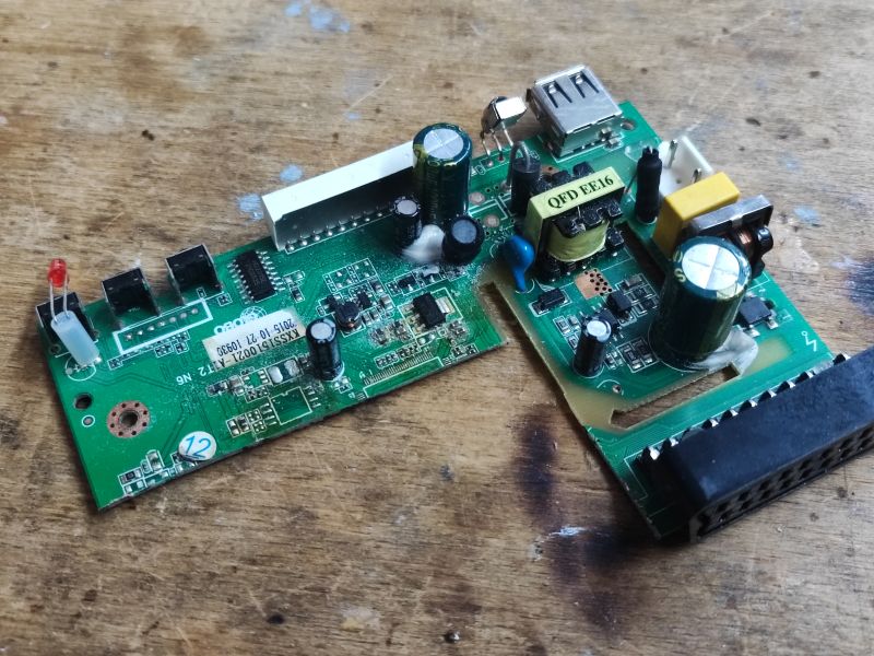
I left the 5V power supply and the inverter providing 3.3V on board. I will remove the SCART connector later. The 1.8V LDO I removed, because it is redundant for me:
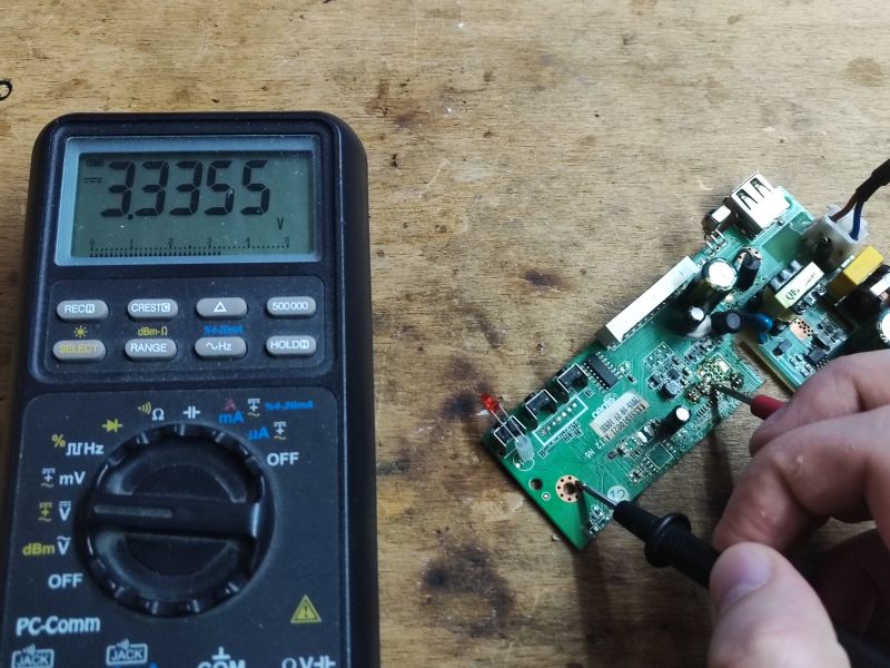
As a new heart I soldered the LN882H WiFi module:
LN882H datasheet, leads, WiFi modules (LN882HK, LN882HKx, LN882), firmware
How to sflash the LN882H with software OpenBeken to free from the cloud
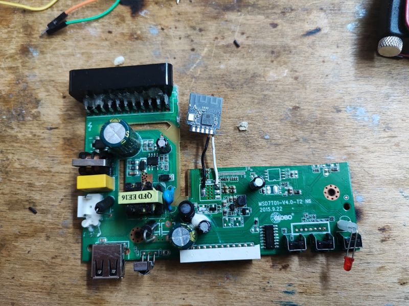
First communication
In the previous section I collected the packages responsible for displaying the time 14 on the display, so here I simply tried to send them. I program the LN882H WiFi module via OTA in OpenBeken. and I compile online on Github , because it's more convenient that way.
In OBK I have a simple software I2C based on the bit-bang method:
Code: C / C++
The bytes sent are from the subject line:
Salae 24MHz logic state analyser for £40 - analysis of unknown LED display protocol Here's the result:
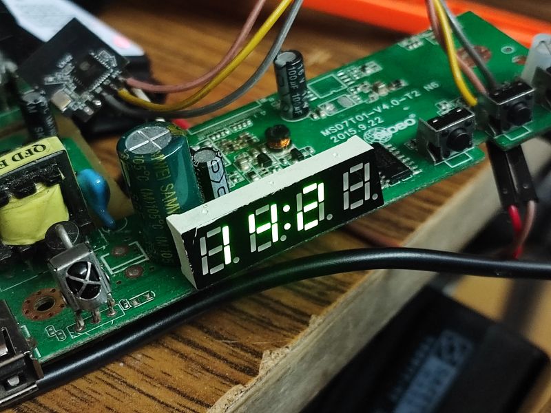
That is, I captured the communication well. Everything works.
I'll just add one important tip here - when sending, it's a good idea to verify with a logic analyser that you are sending what you think you are sending.
Is this a known protocol? The next step was to check if the HD2015 protocol is perhaps compatible with TM1637 or TM1638 or GN6932 - these displays my project already supports.
TM1638 and GN6932 require three lines, CLK, DAT and STB (which, by the way, is also present here, but I don't use it), they are based on SPI protocol. The TM1637 uses two lines, like the HD2015 also does not support addressing, but unfortunately the command bytes themselves are different.
On the other hand, the bit per segment mappings turned out to be identical, my prepared array for TM1637 fits here:
Code: C / C++
I was about to give up with the search, but something touched me to check still TM1650:
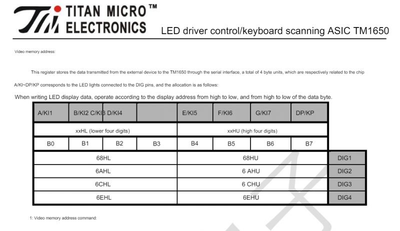
Wait, after all, the address of the digit register agrees - 0x68! The subsequent registers also agree...
And the control register?
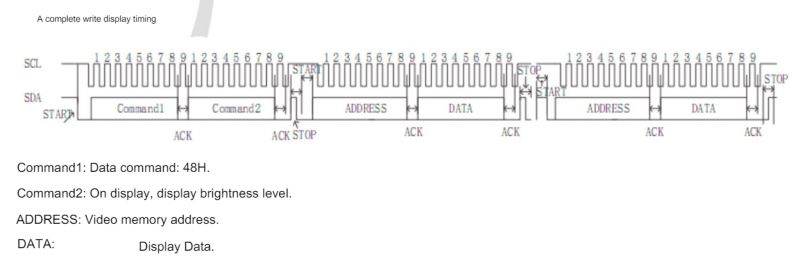
0x48, also agrees. I think that's it! That's even better for me...
Common driver TM1650/HD2015/TM1637/TM1638/GN6932 All these displays operate on a very similar principle. Their communication protocols may be slightly different, the registers are different, but the general idea is the same everywhere.
For this reason, I decided to simply extend the controller that I wrote somewhat in this topic:
7-segment displays on TM1637 - 4 and 6 digits - Arduino, protocol The extended version for TM1637/TM1638/GN6932 I already had, now it was time to add HD2015 (i.e. TM1650).
You only need to change the function that sends the segments:
Code: C / C++
The above function is the version that supports TM1637, TM1638 and GN6932, for these LED drivers the registers match. The HD2015 has slightly different registers, so for a test I simply added a condition to it:
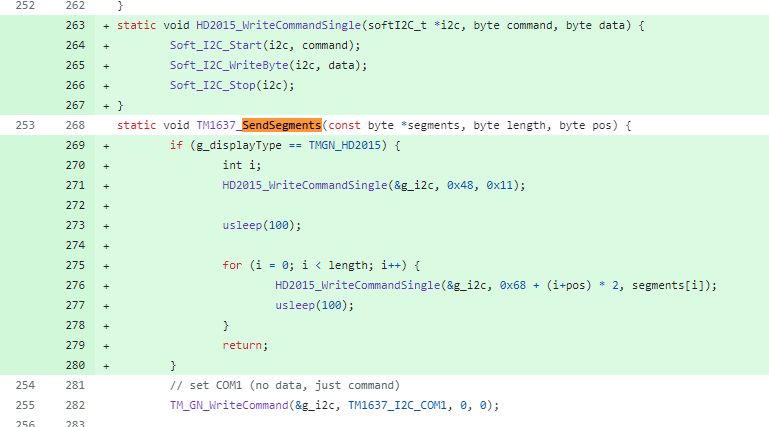
This type of plugging in with a new display into a pre-existing driver has a lot of advantages. Thanks to this, all auxiliary functions I have (setting characters to a position, cleaning, flashing text, countdown) can handle several displays at the same time even "not knowing" what they handle.
I tested the controller and all characters work:
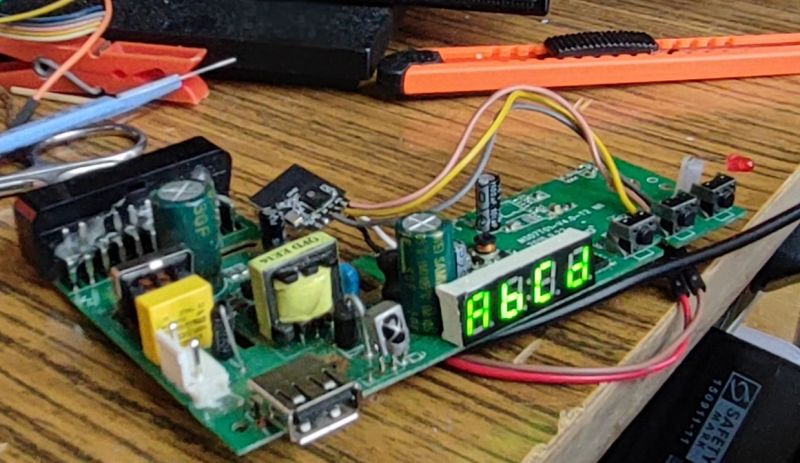
Buttons I also pre-tested and the read values change when I press them.
As far as I'm concerned, my "shared" driver code is here, but it's not publishable at the moment, so you look at it at your own risk:
https://github.com/openshwprojects/OpenBK7231...ob/main/src/driver/drv_tm_gn_display_shared.c
What's next? A fellow from Serbia @DeDaMrAz has a module with TM1628:
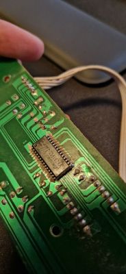
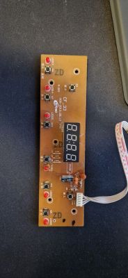 I will soon check if his protocol is also similar to those controllers I have already dealt with.
Summary
Packet capture and analysis showed, that the HD2015 is essentially a TM1650. It seems that their protocols are compatible.
Additionally, I quickly realised that the HD2015/TM1650 support itself is very similar to the TM1637 support (also controlled by two lines) and the TM1638/GN6932 support (with SPI interface - three lines), so in the end I prepared one common driver which supports these four (three?) display controllers.
The operation can therefore be considered successful. I managed to get the display working from the old hardware without prior knowledge of its protocol and pinouts.
PS: With the information that the HD2015 is "suspected" of being compatible with the TM1650, I managed to find a thread: https://wvclub.net/forum/index.php?topic=3189.0 so I guess my idea is confirmed...
I invite you to discuss - have you also run any chips without knowing their communication protocol, by testing with a logic analyser?


Comments