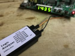
Today I will present step by step the process of analyzing an unknown I2C protocol using the example of a 7-segment display controller with an HD2015E keyboard found on a board from an old DVB-T2 tuner. The aim of the project will be to collect information needed to control HD2015E from Arduino. Here we will intercept communication on SDA/SCL lines with a logic analyzer bought for 10$, decode it as I2C and then try to guess the meaning of individual bytes.
Assumptions
In this case I assume that:
- the reader has basic knowledge of the I2C protocol or similar protocols, knows that it is based on two lines (clock and data), knows that I2C provides two-way communication (writing and reading from the address), knows that depending on whether we are reading or sending data, the Read/Write bit is set (or not), etc
- the reader knows more or less how a 7-segment display works, knows that separate segments are lit, that they create digits, that usually one byte (8 bits) maps to one digit and each bit corresponds to a different segment, etc.
Sale Purchase
This analyzer is really very cheap, you can get it for only PLN 40 in our country - without waiting for a shipment from China:

Let`s see what the seller says about it:
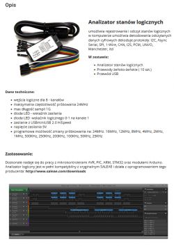
The seller himself admits that this is a "Salae-compatible" analyzer, or colloquially speaking, a clone. I don`t have any complaints about it - for this price... The seller also recommends the link: http://www.saleae.com/downloads, but I already had Pulseview installed.
Installation of Pulseview and drivers
My software of choice is PulseView, PulseView is a graphical interface for Sigrok, the application was written in the QT environment and is available for free:
https://sigrok.org/wiki/PulseView
You can download it here, both in 32 and 64-bit versions:
https://sigrok.org/wiki/Downloads
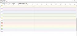
PulseView allows you to capture live data from the analyzer and play back data previously saved to a file. After starting, we are greeted by a minimalist interface:
But it is possible that the analyzer will not be detected yet:
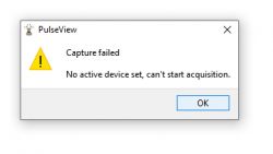
Then you need to install the drivers, I downloaded them from here:
https://zadig.akeo.ie/
I selected my analyzer in the list and started the installation:
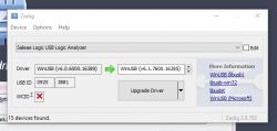
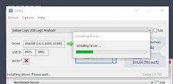
Preparation of equipment - HD2015E LED controllerclass="notranslate">
As part of the Salae demonstration, we will capture I2C communication of a 4-digit, 7-segment LED display controller with additional button support. The display board comes from this topic:
Old DVB-T2 decoder - STB HD N6 - interior, potential for conversion into a DIY clock
Even without knowing the pins of the system, it is easy to know what is connected where, because we have signals output to the pads. Both power supply, CLK and DAT are signed:
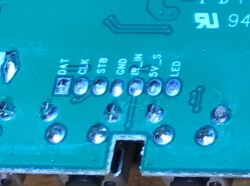
In the photo below you can see that CLK and DAT are connected to the HD2015E pins via two resistors.
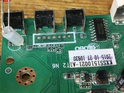
All that remains is to connect the analyzer - but how?
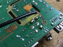
First of all, you should ensure safe power supply to the tested system, not all converters provide isolation from the mains, so I recommend powering everything from the same laptop/computer on which we perform the analysis. . I will not delve into this topic, because the Salae analyzer is discussed here, but as a good rule of thumb, I simply checked that the power supply on the board gives 5V and I decided to solder a 5V cable to the output of this power supply:
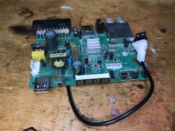
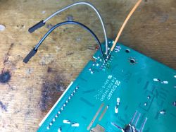
Now you need to connect the analyzer. We connect the channels we are interested in and be sure to do so too mass , we need to have a common benchmark.
Whole system:
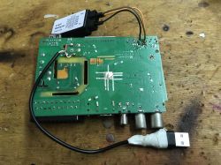
The whole thing will be powered by the USB of one computer, without access to the network.
Capture and analysis
We launch Pulseview and click Run, here:
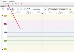
The capture should start. In case of problems, it is worth trying to restart the program, computer and possibly reinstall the drivers, but I assume that you have already installed them before.
If necessary, it is also worth increasing the sampling density:
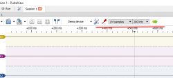
Initially, I had the sampling set so sparsely that the observed I2C was too fast to read.
Only the settings as below gave me the result:

The screenshot shows that something happens from time to time. Capture was enabled with the tuner running. What could this be? I suspect it`s keyboard "polling". The display shows the channel number all the time, so it doesn`t need to be refreshed, so it`s probably not the display. However, I don`t see any interrupt pin for pressing a key (some INT, interrupt), so the MCU probably regularly polls the controller about the status of the keys.
Now it`s time to decode the collected data. We can decode them as I2C:
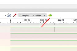
Pulseview decoders are built by the community. We select from the I2C list:
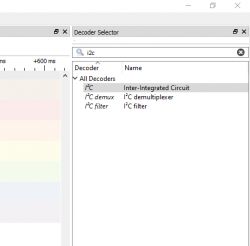
The I2C decoder will appear on the timeline, but you still need to click on it to set the SDA and SCL lines:
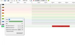
I set it according to the connections from the board:
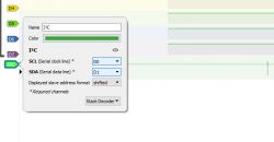
From this point the slow I2C decoding process will begin. Patience! With long timelines this may take some time.
Communication analysis - idle state
By "idle state" I mean the equipment is turned on but no operations are performed. A channel is simply selected and the user does nothing.
Nevertheless, from time to time something happens and we capture something:

Let`s zoom in and see what`s being transferred:
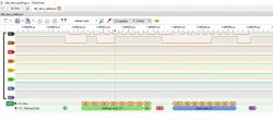
It seems that one address is given (it is not the address of the device, but of the register, probably the protocol here is not actually I2C, I have already seen versions without the device address) and then data from this address is read.
I suspect that this is asking the system about the state of the keys, the so-called "polling". This chip does not have an INT/Interrupt pin to indicate that something has happened, so the MCU must regularly query it about the state of the keys to see if anything has changed.
The state of the keys is read from register 0x27 (or: command 0x27).
The response 0x07 is the same every time, but will it change when I hold down a key?
Communication analysis - "next channel" key pressed
So we repeat the capture, this time holding down the "next channel" key, of course the key on the housing, not on the remote control.
Now we batch capture two communication sessions together
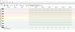
Let`s take a closer look at them. First, the package I suspected of handling keys;
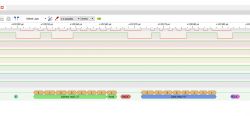
The read value changes. The register is still 0x27, but now we read 0x47 and not 0x07.
Bitwise it is:
- 0x07 -> 0000 0111
- 0x47 -> 0100 0111
So one key equals one bit, as expected. Probably pressing the second key would light a different bit.
But that`s not all, here is the second package, let`s take a look at it:
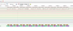
There`s a lot going on here. Basically I see here:
- setting the register with address 0x24 to the value 0x71 (repeated)
- subsequent setting of registers with addresses 0x34, 0x35, 0x36 etc. to different values
I would assume that 0x24 is the display control register and the registers starting from 0x34 are the registers of displayed digits. The display has 4 digits and we have subsequent entries for 0x34, 0x35, 0x36 and 0x37. Additionally, the first two values written to these registers are 0x00, which agrees with what I see on the display, because I see that the first two digits are off.
Here`s the same thing, but at a higher magnification:


Oh, I almost forgot - for convenience, let`s hide the unnecessary lines:
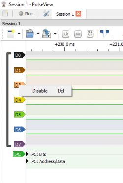
We just click on them and select "Disable" to hide them.
Ok, now let`s see what the first channel number is sent to the display, i.e. the first three digits are off and then the character 1.
I deliberately scrolled to the last channel so that I could access channel 1 with one press of the key.
Results:

Following suit, I also captured subsequent channel changes, always one further, to be able to compare the segment codes sent .
Here`s the finished comparison:
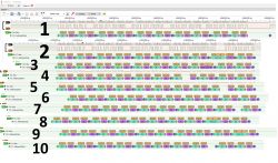
What do we see here?
- for 1, the registers are set to 0x00 0x00 0x00 0x06
- for 2, the registers are set to 0x00 0x00 0x00 0x5B
- for 3, the registers are set to 0x00 0x00 0x00 0x4F
- for 4, the registers are set to 0x00 0x00 0x00 0x66
- for 5, the registers are set to 0x00 0x00 0x00 0x6D
- for 6, the registers are set to 0x00 0x00 0x00 0x7D
- for 7, the registers are set to 0x00 0x00 0x00 0x07
- for 8, the registers are set to 0x00 0x00 0x00 0x7F
- for 9, the registers are set to 0x00 0x00 0x00 0x6F
- for 10, the registers are set to 0x00 0x00 0x06 0x3F
You can see here that in the case of 10, the digit 1 also appears earlier and has the same code 0x06 as in the last place.
Now we can determine which bits are which segments.
Let`s start by comparing 0 (0x3F) and 8 (0x7F):
- 0x3F -> 0011 1111
- 0x7F -> 0111 1111
So the middle beam is the seventh bit.
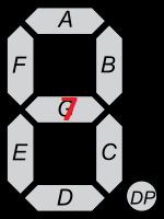
Now let`s compare 5 and 6, because 5 is 6 without one segment:
- 0x6D -> 0110 1101
- 0x7D -> 0111 1101
We can see that the difference between them is the bit in position 5:
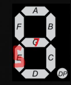
In this way, we can also determine the roles of other segments.
I will also add that I am surprised that the address and the digit value are always sent separately. After all, as a rule, you can only send the address once and then the bytes one by one, and they will be written to subsequent memory cells. Does HD2015 not support it, or maybe the creator of the program simply didn`t use it?
Communication analysis - standby mode
Surprisingly, most of what happens on this line is in the standby state, i.e. when the decoder is turned off. This is because a clock then appears. At the time of capture it showed 14:29:
But I won`t decode it for now, because it`s setting the numbers the same as I discussed earlier:
You could also look here where the colon is sent - perhaps it has a separate register or is attached to one of the digits, after all, the display is 7-segment and the registers are 8-bit, so one free bit is available.
Summary
I really liked this logic analyzer. I have been using it for some time now and at the same time I really regret that I didn`t have it 5 or so years ago when I started my adventure with microcontrollers. It would certainly help me more effectively diagnose potential problems with the implementation of I2C or other protocols.
I am also very satisfied with the computer application, Pulseview - you can even write plugins for it in Python, I once modified one script (WS2812 decoding) to make it compatible with SM15155E, details here .
As for the analyzed protocol itself, the first thing that catches the eye is the lack of addressing of the system, which means that it is not compatible with I2C and we cannot place several such devices on the bus. It reminds me very much of the protocol TM1637 , wouldn`t it be practically the same?
Apart from that - no complaints, very simple protocol, maybe in the next part I will try to implement it on Arduino.
Have you used this or similar logic analyzers? Do you think they are useful? I invite you to discuss.
Cool? Ranking DIY Helpful post? Buy me a coffee.


