[CBU]BK7231N GEYA GRD9L-W Wifi MCB Controller Din Rail Auto Circuit Breaker Recloser
Wanted to incorporate the following device into my MQTT Network:
https://vi.aliexpress.com/item/1005006309773987.html

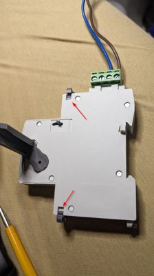
Actually I wanted to detach the device and use with a RCB. Detaching was simple as there were two retaining latches at the top and the bottom.


It came with Tuya Firmware V1.0.5
I was able to use cloutclutter to flash with OpenBeken using following profile:
Tuya configuration file looked like this:
Suggested config for OpenBeken was like this:
I really do not understand what the following statement means:
And the Tuya section starts at UNCOMMON POSITION 0
Since the device is a motorized device there are forward and reverse relays:
"rl_on1_pin":"15",
"rl_off1_pin":"17",
After experimenting I figured out that
Bridge FORWARD
Bridge REVERSE
GPIO configuration will make this work.
Then there is this PIN which controls the Automatic/Manual control.
If I set it to ON, then above Forward/Reverse actions work.
"back_vol_pin":"14",
I set PINs 15/17 (Bridge) as Channel 1 and PIN 14 (Relay) as Channel 2

So far so good.
Then there are 3 PINs for a Hall Effect Sensor (guessed from the naming) of pins):
"hall_on_pin":"16",
"hall_off_pin":"22",
"hall_mid_pin":"20",
I configured these as dInput as Channels 4,5,6 and I was able to observe the transitions when the relays are operated.
Switch OFF to ON Transition:
Switch ON to OFF Transition
Then there is LED PIN:
"netled1_pin":"24",
and a Button PIN:
"bt1_pin":"26",
The LED has two colors. When using the Auto position with Tuya App the Green/Red status colors were shown. However I was not able to identify how to obtain the RED LED.
When I moved the arm manually to off position it seems to trigger the RED LED but if I operate the arm using the web GUI, the RED LED does not get litup when in OFF Position.
Still playing with this.
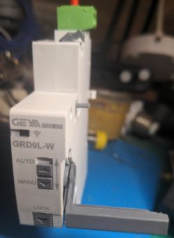
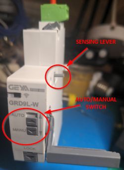
When AUTO/MANUAL SWITCH is moved DOWN (MANUAL) I see the following which confirms that PIN26 is assigned to that switch
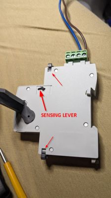
There is a SENSING LEVER which engages with a mechanism in the attached breaker to detect the ON/OFF position from the breaker also. However I could not figure out yet on how it is detected.


So I want to put these together in a script to make it work like original setup.
May need some help.
1. Probably I need to match Button 26 with Relay 14. That is the AUTO/MANUAL switch enables/disables the FWD/REVERSE relay operation
2. Figure out how to programmatically turn on RED LED
3. Make use of the HALL EFFECT SENSOR inputs to detect the current state? Suppose there was a manual operation of the switch and when software becomes active how can I detect the actual physical state of the switch?
Added after 9 [hours] 47 [minutes]:
I found the same product with no position sensor on eBay:
https://www.ebay.com/itm/395819581447

https://vi.aliexpress.com/item/1005006309773987.html

Actually I wanted to detach the device and use with a RCB. Detaching was simple as there were two retaining latches at the top and the bottom.


It came with Tuya Firmware V1.0.5
I was able to use cloutclutter to flash with OpenBeken using following profile:
     > 1.0.5 - BK7231N / oem_bk7231n_cutout_self_switch

[?] Select the brand of your device: EARU
 > EARU

[?] Select the article number of your device: EAWCT-J Circuit Breaker with energy meter v1.0.5
 > EAWCT-J Circuit Breaker with energy meter v1.0.5
Tuya configuration file looked like this:
{
   "back_vol_lv":"0",
   "bt1_pin":"26",
   "remote_ctrl_mode":"0",
   "rl1_drvtime":"100",
   "hall_mid_pin":"20",
   "net_trig":"2",
   "rl_on1_pin":"15",
   "jv":"1.0.0",
   "netled1_lv":"1",
   "netled_reuse":"0",
   "bt1_type":"0",
   "temp_fun_en":"0",
   "hall_on_pin":"16",
   "hall_off_pin":"22",
   "nety_led":"1",
   "rl_off1_pin":"17",
   "bt1_lv":"0",
   "reset_t":"5",
   "netled1_pin":"24",
   "hall_off_lv":"0",
   "rl_on1_lv":"1",
   "hall_mid_lv":"0",
   "module":"CBU",
   "ch_cddpid1":"9",
   "hall_on_lv":"0",
   "ch1_stat":"2",
   "back_vol_pin":"14",
   "rl1_type":"2",
   "ch_num":"1",
   "rl_off1_lv":"1",
   "netn_led":"0",
   "ch_dpid1":"1",
   "crc":"127"
}
Suggested config for OpenBeken was like this:
Device configuration, as extracted from Tuya:
- Button (channel 1) on P26
- Bridge Relay On (channel 1) on P15
- Bridge Relay Off (channel 1) on P17
- WiFi LED on P24
Device seems to be using CBU module, which is using BK7231N.
And the Tuya section starts at UNCOMMON POSITION 0
I really do not understand what the following statement means:
And the Tuya section starts at UNCOMMON POSITION 0
Since the device is a motorized device there are forward and reverse relays:
"rl_on1_pin":"15",
"rl_off1_pin":"17",
After experimenting I figured out that
Bridge FORWARD
Bridge REVERSE
GPIO configuration will make this work.
Then there is this PIN which controls the Automatic/Manual control.
If I set it to ON, then above Forward/Reverse actions work.
"back_vol_pin":"14",
I set PINs 15/17 (Bridge) as Channel 1 and PIN 14 (Relay) as Channel 2

So far so good.
Then there are 3 PINs for a Hall Effect Sensor (guessed from the naming) of pins):
"hall_on_pin":"16",
"hall_off_pin":"22",
"hall_mid_pin":"20",
I configured these as dInput as Channels 4,5,6 and I was able to observe the transitions when the relays are operated.
              on-16 6        | 0  |  1 | SWITCH ON
            /                |    |    |
           /                 |    |    |
          O---- mid-20 5     |1->0|1->0|
           \                 |    |    |
            \                |    |    |
              off-22 4       | 1  | 0  | SWITCH OFF
Switch OFF to ON Transition:
Info:MQTT:Channel has changed! Publishing 1 to channel 1
Info:DRV:Bridge Driver: 681406 : FORWARD PULSE
Info:GEN:No change in channel 1 (still set to 1) - ignoring

Info:GEN:CHANNEL_Set channel 5 has changed to 1 (flags 0)

Info:MQTT:Channel has changed! Publishing 1 to channel 5
Info:GEN:CHANNEL_Set channel 4 has changed to 1 (flags 0)

Info:MQTT:Channel has changed! Publishing 1 to channel 4
Info:GEN:CHANNEL_Set channel 6 has changed to 0 (flags 0)

Info:MQTT:Channel has changed! Publishing 0 to channel 6
Info:DRV:Bridge Driver: 682006 :PULSE Complete. HOLD
Info:GEN:CHANNEL_Set channel 5 has changed to 0 (flags 0)

Info:MQTT:Channel has changed! Publishing 0 to channel 5
Switch ON to OFF Transition
Info:MQTT:Channel has changed! Publishing 0 to channel 1
Info:DRV:Bridge Driver: 727234 : REVERSE PULSE
Info:GEN:No change in channel 1 (still set to 0) - ignoring

Info:GEN:CHANNEL_Set channel 6 has changed to 1 (flags 0)

Info:MQTT:Channel has changed! Publishing 1 to channel 6
Info:GEN:CHANNEL_Set channel 5 has changed to 1 (flags 0)

Info:MQTT:Channel has changed! Publishing 1 to channel 5
Info:GEN:CHANNEL_Set channel 4 has changed to 0 (flags 0)

Info:MQTT:Channel has changed! Publishing 0 to channel 4
Info:DRV:Bridge Driver: 727834 :PULSE Complete. HOLD
Info:GEN:CHANNEL_Set channel 5 has changed to 0 (flags 0)

Info:MQTT:Channel has changed! Publishing 0 to channel 5
Then there is LED PIN:
"netled1_pin":"24",
and a Button PIN:
"bt1_pin":"26",
The LED has two colors. When using the Auto position with Tuya App the Green/Red status colors were shown. However I was not able to identify how to obtain the RED LED.
When I moved the arm manually to off position it seems to trigger the RED LED but if I operate the arm using the web GUI, the RED LED does not get litup when in OFF Position.
Still playing with this.
When AUTO/MANUAL SWITCH is moved DOWN (MANUAL) I see the following which confirms that PIN26 is assigned to that switch
Info:GEN:26 Button_OnInitialPressDown
Info:GEN:26 Button_OnLongPressHoldStart
There is a SENSING LEVER which engages with a mechanism in the attached breaker to detect the ON/OFF position from the breaker also. However I could not figure out yet on how it is detected.


So I want to put these together in a script to make it work like original setup.
May need some help.
1. Probably I need to match Button 26 with Relay 14. That is the AUTO/MANUAL switch enables/disables the FWD/REVERSE relay operation
2. Figure out how to programmatically turn on RED LED
3. Make use of the HALL EFFECT SENSOR inputs to detect the current state? Suppose there was a manual operation of the switch and when software becomes active how can I detect the actual physical state of the switch?
Added after 9 [hours] 47 [minutes]:
I found the same product with no position sensor on eBay:
https://www.ebay.com/itm/395819581447


Comments
cool. please post your template JSON from the web application so I can add to the device list. https://obrazki.elektroda.pl/6256771300_1735549084_thumb.jpg [Read more]
I am not sure whether we should publish it yet as I am still trying to figure out things. This is my test config. { "vendor": "Tuya", "bDetailed":... [Read more]
Ah ok, sure. Will hold off for now. [Read more]
Objective: To detect the position of the AUTO/MANUAL Switch. https://obrazki.elektroda.pl/8667231700_1735625090_thumb.jpg If I configure "bt1_pin":"26", as Btn Then when I switch... [Read more]
I don't know enough about this kind of device and the use of the BridgeREV/BridgeFWD pin functions to be of any real help There are 5 other devices in the device list that appear to make use of Bridgexx.... [Read more]
Thanks. In fact I picked up the Bridgexx usage from one of these threads. The Bridge Relay is actually a relay which holds (latches) its position without consuming power hence not dispersing heat. My... [Read more]