Aqia Smart Plug F3202-US Teardown and Home Assistant Integration Guide
This is a teardown for an Aqia Model F3202-US Wifi smart outlet. This outlet is controlled via a WB2S module.
Item description page from MicroCenter
This was my first reformatting of any sort of smart appliance. I made this work with Home Assistant via the MQTT protocol. I got four of them on sale for $5 each, and was able to convert them all.
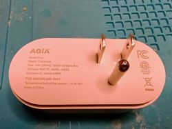
Here is the back of the unit.
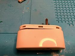
Opened a bit so you can see where to pry the case.
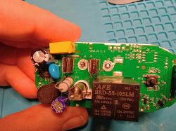
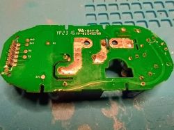
The top side of the control board (A point of pride for me - the yellow C2 was ALREADY melted when I opened it!) This is after desoldering the H3 and H4 contacts.
Desoldering those was pretty much the hardest part of this entire process. There is a very large mound of solder on them and you either have to use a LOT of desoldering braid, or a vacuum de-soldering tool to work on them. I did four of these sockets and ended up heat-deforming the case on all four.
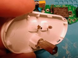
You can see the desoldered posts here. Notice the melted plastic. Also notice the rings around the posts that are still attached.
Once you have the controller board separated from the housing, you can access the back of the control board and see where the WB2S is attached.
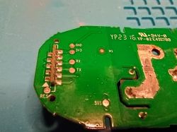
At first, I tried to talk to the WB2S directly, but the circuitry on the controller board was messing me up:
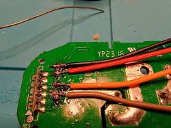
So I followed the advice given here and removed the WB2S board and worked directly with it.
That removal process is demonstrated very well in this youtube video at around 1 minute and 40 seconds:
As I sit looking at this now, I realize I used the WORST possible colored wires to make a post about this board.
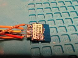
Please notice that in this picture, there are leads attached to VBAT, GND, 1RX, and 1TX on this side of the WB2S.
There are actually TWO leads attached to GND here, one which goes to the UART programmer and the other to the push button shown below.
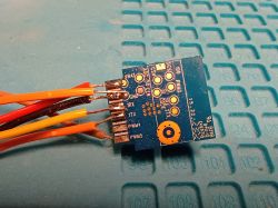
On the OTHER side of the WB2S, there is a lead attached to CEN. This also goes to the button shown below.
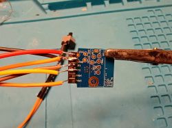
This is the best picture I could get that shows the button. This is a momentary, Normally Open button switch. This allows for an EASY WAY
to activate the programming mode on the WB2S chip when are using the flashing tool. I tried several times to do it with just touching the wires together, or touching the chip at just the right time, but this actually makes it simple and much less of a hassle.
I used a cheap UART programmer with the output set to 3.3V to hook up to my Windows PC.
UART Programmer listing on Amazon.com

I used those DuPont breadboard wires to make connecting it easy.
VOUT -> VBAT, GND -> GND, TXD -> 1RX, RXD -> 1TX (cross over the TX/RX pins)
I would add the steps for running the software, but I tried to follow two of the older posts, and the software had changed enough to make it harder instead of easier.
The basic steps are:
1 - Download the right firmware file
2 - Connect the UART programmer to Windows (plug it into a USB port)
3 - Start the flashing software
4 - Backup the current firmware on the WB2S to a file on your PC (there's a button on the screen)
5 - Write the new firmware to the WB2S (there's a button on the screen)
6 - Write the configuration file to map the pins to the functions (there's a button on the screen)
The important part for this switch or any device is the "pins" and what they do. This software will send signals to pins based on commands.
So if your first relay is on pin 24 of channel 1, you need to configure this WB2S to know that when it gets the "turn relay 1 on" command, it knows to set pin 24 to high.
For this switch there are four controls:
"Btn", which is the "is this switch on?" light inside the little button on the front
"LED", which is the blinky light when it's connecting to the network
"Rel", which is the Relay for the power
Two things:
This switch only has one outlet, so everything is "channel" 1. If you had more outlets in the device, they would each get a new channel.
This switch treats "LED" like most other devices on this list treat the "WifiLED." Not sure why, but trial and error showed it to be the case. So to see the button light up with you turn on the switch, you need to map the "Btn" command.
The mappings are
Pin 11 - LED
Pin 24 - Rel
Pin 26 - Btn
The JSON file that makes this go more quickly is included here. You'll use the firmware writer program to flash it to the WB2S
(copying without the syntax tag so you don't need to log in to see it)
{
"reset_t":"3",
"rl1_lv":"1",
"netled_lv":"1",
"bt_type":"0",
"bt1_pin":"26",
"ch_flag1":"1",
"inch_dp":"44",
"rand_dpid":"43",
"net_trig":"2",
"module":"WB2S",
"ch_cddpid1":"9",
"led_)Bgw_wsmdp":"40",
"jv":"1.1.5",
"init_conf":"38",
"lock_dp":"41",
"cyc_dpid":"42",
"ch_num":"1",
"netled_pin":"11",
"total_stat":"2",
"reuse_led_m":"1",
"rl_type":"0",
"rl1_pin":"24",
"ch_dpid1":"1",
"bt1_lv":"0",
"crc":"100"
}
The requirements for posting a teardown say to include the JSON file from the Web Application main page, so I'm including that here as well. I think you'll see it's the template with only the pins changed
(copying without the syntax tag so you don't need to log in to see it)
{
"vendor": "Tuya",
"bDetailed": "0",
"name": "Full Device Name Here",
"model": "enter short model name here",
"chip": "BK7231T",
"board": "TODO",
"flags": "1024",
"keywords": [
"TODO",
"TODO",
"TODO"
],
"pins": {
"11": "LED;1",
"24": "Rel;1",
"26": "Btn;1"
},
"command": "",
"image": "https://obrazki.elektroda.pl/YOUR_IMAGE.jpg",
"wiki": "https://www.elektroda.com/rtvforum/topic_YOUR_TOPIC.html"
}
I'm sorry I can NOT remember how I originally got the pins configured. I think I used the web page that becomes available after the socket connects to your network. From there, you can change local settings. Using the original firmware backup, I was able to poke around and see which pins has something defined. Then by trying different values on those pins in the configuration, I could make it work. Then I put those configurations into an OBK template JSON file and loaded that using the firmware writer. For subsequent sockets, I could just load that same JSON file and it worked.
Hopefully, this will help someone else get these up and running. They are nice because they handle a full 15A, whereas most of the wifi sockets are limited to 10A.
If you are a tinkerer, feel free to contact me at spamdump43230(_at_)gmail.com to let me know if I left anything out or to make corrections.
Item description page from MicroCenter
This was my first reformatting of any sort of smart appliance. I made this work with Home Assistant via the MQTT protocol. I got four of them on sale for $5 each, and was able to convert them all.
Here is the back of the unit.

Opened a bit so you can see where to pry the case.

The top side of the control board (A point of pride for me - the yellow C2 was ALREADY melted when I opened it!) This is after desoldering the H3 and H4 contacts.
Desoldering those was pretty much the hardest part of this entire process. There is a very large mound of solder on them and you either have to use a LOT of desoldering braid, or a vacuum de-soldering tool to work on them. I did four of these sockets and ended up heat-deforming the case on all four.

You can see the desoldered posts here. Notice the melted plastic. Also notice the rings around the posts that are still attached.

Once you have the controller board separated from the housing, you can access the back of the control board and see where the WB2S is attached.


At first, I tried to talk to the WB2S directly, but the circuitry on the controller board was messing me up:

So I followed the advice given here and removed the WB2S board and worked directly with it.
That removal process is demonstrated very well in this youtube video at around 1 minute and 40 seconds:
As I sit looking at this now, I realize I used the WORST possible colored wires to make a post about this board.
Please notice that in this picture, there are leads attached to VBAT, GND, 1RX, and 1TX on this side of the WB2S.
There are actually TWO leads attached to GND here, one which goes to the UART programmer and the other to the push button shown below.

On the OTHER side of the WB2S, there is a lead attached to CEN. This also goes to the button shown below.

This is the best picture I could get that shows the button. This is a momentary, Normally Open button switch. This allows for an EASY WAY
to activate the programming mode on the WB2S chip when are using the flashing tool. I tried several times to do it with just touching the wires together, or touching the chip at just the right time, but this actually makes it simple and much less of a hassle.

I used a cheap UART programmer with the output set to 3.3V to hook up to my Windows PC.
UART Programmer listing on Amazon.com

I used those DuPont breadboard wires to make connecting it easy.
VOUT -> VBAT, GND -> GND, TXD -> 1RX, RXD -> 1TX (cross over the TX/RX pins)
I would add the steps for running the software, but I tried to follow two of the older posts, and the software had changed enough to make it harder instead of easier.
The basic steps are:
1 - Download the right firmware file
2 - Connect the UART programmer to Windows (plug it into a USB port)
3 - Start the flashing software
4 - Backup the current firmware on the WB2S to a file on your PC (there's a button on the screen)
5 - Write the new firmware to the WB2S (there's a button on the screen)
6 - Write the configuration file to map the pins to the functions (there's a button on the screen)
The important part for this switch or any device is the "pins" and what they do. This software will send signals to pins based on commands.
So if your first relay is on pin 24 of channel 1, you need to configure this WB2S to know that when it gets the "turn relay 1 on" command, it knows to set pin 24 to high.
For this switch there are four controls:
"Btn", which is the "is this switch on?" light inside the little button on the front
"LED", which is the blinky light when it's connecting to the network
"Rel", which is the Relay for the power
Two things:
This switch only has one outlet, so everything is "channel" 1. If you had more outlets in the device, they would each get a new channel.
This switch treats "LED" like most other devices on this list treat the "WifiLED." Not sure why, but trial and error showed it to be the case. So to see the button light up with you turn on the switch, you need to map the "Btn" command.
The mappings are
Pin 11 - LED
Pin 24 - Rel
Pin 26 - Btn
The JSON file that makes this go more quickly is included here. You'll use the firmware writer program to flash it to the WB2S
Code: JSON
(copying without the syntax tag so you don't need to log in to see it)
{
"reset_t":"3",
"rl1_lv":"1",
"netled_lv":"1",
"bt_type":"0",
"bt1_pin":"26",
"ch_flag1":"1",
"inch_dp":"44",
"rand_dpid":"43",
"net_trig":"2",
"module":"WB2S",
"ch_cddpid1":"9",
"led_)Bgw_wsmdp":"40",
"jv":"1.1.5",
"init_conf":"38",
"lock_dp":"41",
"cyc_dpid":"42",
"ch_num":"1",
"netled_pin":"11",
"total_stat":"2",
"reuse_led_m":"1",
"rl_type":"0",
"rl1_pin":"24",
"ch_dpid1":"1",
"bt1_lv":"0",
"crc":"100"
}
The requirements for posting a teardown say to include the JSON file from the Web Application main page, so I'm including that here as well. I think you'll see it's the template with only the pins changed
Code: JSON
(copying without the syntax tag so you don't need to log in to see it)
{
"vendor": "Tuya",
"bDetailed": "0",
"name": "Full Device Name Here",
"model": "enter short model name here",
"chip": "BK7231T",
"board": "TODO",
"flags": "1024",
"keywords": [
"TODO",
"TODO",
"TODO"
],
"pins": {
"11": "LED;1",
"24": "Rel;1",
"26": "Btn;1"
},
"command": "",
"image": "https://obrazki.elektroda.pl/YOUR_IMAGE.jpg",
"wiki": "https://www.elektroda.com/rtvforum/topic_YOUR_TOPIC.html"
}
I'm sorry I can NOT remember how I originally got the pins configured. I think I used the web page that becomes available after the socket connects to your network. From there, you can change local settings. Using the original firmware backup, I was able to poke around and see which pins has something defined. Then by trying different values on those pins in the configuration, I could make it work. Then I put those configurations into an OBK template JSON file and loaded that using the firmware writer. For subsequent sockets, I could just load that same JSON file and it worked.
Hopefully, this will help someone else get these up and running. They are nice because they handle a full 15A, whereas most of the wifi sockets are limited to 10A.
If you are a tinkerer, feel free to contact me at spamdump43230(_at_)gmail.com to let me know if I left anything out or to make corrections.


Comments
Good job, regarding the desoldering those two huge pins, I would try to mix the Pb-free solder with some old classic leaded solder to lower the melting point of the whole mix. Then braid/solder wick, as... [Read more]
https://obrazki.elektroda.pl/7190336400_1735988292_thumb.jpg https://github.com/OpenBekenIOT/webapp/commit/ac72759981b9179279fc0674d82e4772a37f6736 [Read more]