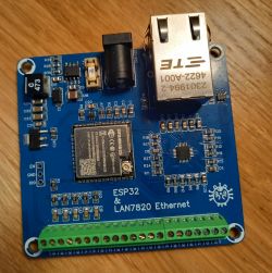
ESP32 with Ethernet - Compatible with ESPHome.
 .
.
Hi,
As the summer season is approaching, I have decided to build a weather station (or rather a "motherboard" for it) to control the irrigation system and also to allow a quick view of current parameters such as temperature, humidity or pressure, with the possibility of extending the functionality.
For a while I was looking for ready-made solutions - the most suitable for me were Olimex and LILYGO modules available for about $20-25 with active PoE to which I would attach individual sensors. However, they lacked screw connectors for easy connection of further sensors, which prompted me to make my own board (something like a mother board with such connectors). At some point I thought: since I would have to design a PCB anyway, why not make my own solution and learn something in the process?
This is how the first version of the design and the first PCB came about, which initially included an active PoE circuit on the LTC4267. I eventually abandoned it for a number of reasons, which led to the development of a second version - the one I am presenting now.
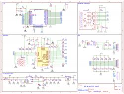
Schematic:
 .
.
I chose the ESP32 WROOM-32UE as the main CPU, which takes up less board space due to the lack of an antenna, which I don't need anyway. The downside of this is the slightly increased price of the ESP32 WROOM compared to the regular ESP32. In addition, the use of ESP32 ensures full compatibility with ESPHome, making it much easier to integrate everything into the Home Assistant. The LAN7820 chip (schematic copied from the internet), also chosen for its ESPHome compatibility, is responsible for Ethernet communication.
The inverter is based on the MIC4684, which I just happened to have on hand. It provides up to 2A of current, which is more than enough for my needs. The chip can be powered at up to 32V, which allows you to use a higher voltage than the standard 5V - useful when using passive PoE splitters.
Why did I abandon active PoE? For several reasons:
1. cost, active PoE requires quite a lot of additional components, such as an isolated DC-DC converter, a special MagJack or a signal transformer. These components alone cost more than all the rest of the circuitry on the board.
2. requires a suitable switch.
3. in the first version, the PHY chip was not sufficiently protected, which resulted in its failure after several connections and disconnections of the Ethernet cable - a known problem in PoE solutions.
4. On Chinese portals you can buy an active PoE splitter with an isolated 12V output for about $3.5 - about the cost of the flyback transformer alone for me.
As an Ethernet socket, I chose the 2301994-2 from TE, which has an integrated signal transformer, simplifying the PCB design. It is not one of the cheapest, but I managed to get some at a good price.
The last thing worth discussing is the I2C amplifier, based on the LTC4311, this is optional, but it costs nothing to put a footprint on the PCB and can be useful when you want to connect devices/sensors that are a little further away.
If anyone would be interested I provide a link to a github with schematics, PCB fabrication files and the sample YAML for ESPHome needed to run the PHY.
https://github.com/aycarambaa/ESP32-Lan7820-Ethernet.git


Comments
Thank you for sharing your project. And what made you give up on WiFi alone? Just the desire to provide power, or the stability/security? I'll tell you, I have a couple of ESPs going non-stop and I'm... [Read more]
For this type of solution, it is also worth looking at ready-made modules based on ESP32-P4, e.g. ESP32-P4-NANO. https://www.waveshare.com/wiki/ESP32-P4-Nano-StartPage From the Arduino Core website there... [Read more]
I gave up on Wi-Fi because of the distance. In addition, twisted pair cable had already been laid to the cameras, over which I would have had to run power anyway. As for the stability of the WiFi on the... [Read more]
It is very nice to look at such an aesthetically designed board :-) . [Read more]
. Could you please elaborate on this? The current is received on the primary side of the transformer (cable side) and the PHY is on the secondary side. [Read more]
. Confirmation. A friend has a fancy Asus router and in the schedule he has a reboot set once a week. Otherwise he has been experiencing hang-ups. [Read more]
When unplugging/plugging the rj45 plug, there can sometimes be a momentary 'spike' of voltage on the transformer, in the previous version I protected against this by adding TVS diodes on the RX and TX... [Read more]
That's right, I also have an esp-based solution at my company that monitors the temperature in my server rooms and when the value is exceeded, it sends me an sms notification, and as far as wifi is concerned,... [Read more]
I glanced at the layout out of curiosity. As I understand it, the connector at the bottom is only the input for signals and power supply ? In the case of the output for e.g. 3.3V it is better to derive... [Read more]
The connectors at the bottom are signal inputs/outputs, you are right, the via could have been moved a few mm to the left. The area around C24, C22, C23 I left that filling as such "isolating" the feedback... [Read more]
ESD protection in the ESP itself may not be able to help. The system is too far away. The potential landing will extend across the board and may "mess up". Therefore, it would be best to connect along... [Read more]