ESP32 and Remote Control Transceiver (RMT) - tutorial, first steps, WS2812 control
 .
.
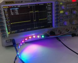
The Remote Control Transceiver (RMT) on the ESP32 is a special hardware module that allows precise generation and reception of timing signals such as IR and RF control. Here I will show how to run it and use it to operate the WS2812B diodes, which are known to need a fairly precise waveform at the DI input to obtain colour data. By the way, we will look at the generated waveforms on an oscilloscope.
To begin with, I will remind you of the previous topics in the series. The first, most important discussion of the WS2812 and similar:
PIC18F45K50 as WS2812 LED strip driver (theory+library) .
A side topic, a method with hardware SPI and DMA:
Controlling WS2812 diodes via SPI with DMA - using MOSI to generate timings .
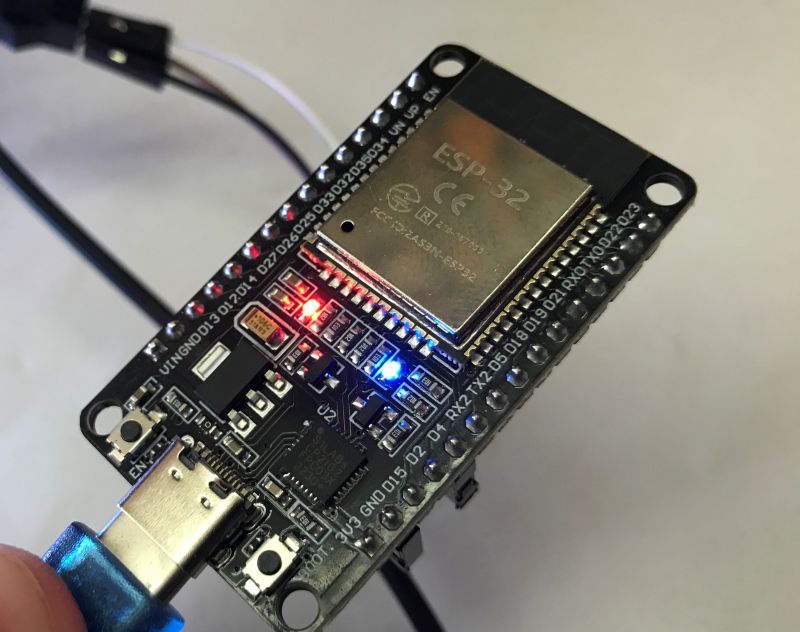
This time I will make the program based on ESP32:
 .
.
I start the presentation with my classic code integrating WiFiManager and OTA (batch update via WiFi):
Code: C / C++
You also need to refer to the documentation I am relying on here:
https://docs.espressif.com/projects/esp-idf/e...able/esp32/api-reference/peripherals/rmt.html
We start the adventure by including the library header:
Code: C / C++
Then we need to initialise the RMT. Initialisation includes:
- mode setting (RMT_MODE_TX for transmit or RMT_MODE_RX for receive)
- channel selection (RMT_CHANNEL_0 to RMT_CHANNEL_7)
- setting the number of the GPIO pin with which the RMT will interact (GPIO_NUM_4 enumeration, which simplifies to a numeric 4)
- configuration of the number of memory blocks for data storage
- configuration of the transmit mode, including enabling/disabling loop, carrier, or setting the idle level (low or high)
- clock divider configuration, as high and low state times are expressed in cycles .
The default clock input is APB_CLK, which is 80MHz. If we set the clock divider to 2, the RMT clock is 40MHz. Then one cycle is 25 ns.
Code: C / C++
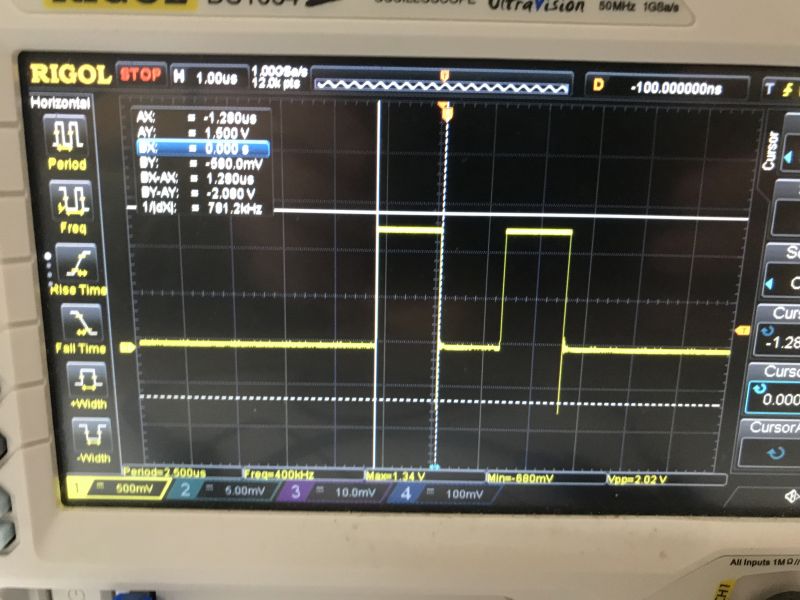
Now you can transmit something, bearing in mind that one cycle is 25 ns. Since one cycle is 25 ns, let's choose a value of 50 to try, which will give us 50*25ns = 1.25 μs. So now we set up an array of objects rmt_item32_t , where each object describes one high and one low state separately. We have control over when and how long these states last. For both low and high I entered 50. We then set this data and send.
Code: C / C++
I connected both functions to setup and loop respectively.
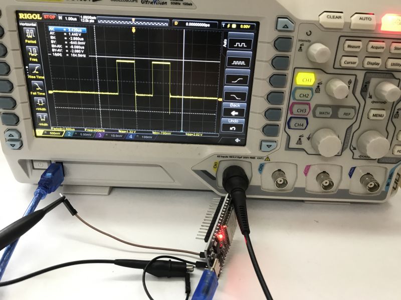
Now the oscilloscope can be connected. You will need Single mode, pulse trigger, we need to catch that moment when the ESP will send the data:
 .
.
 .
.
I used the Cursor function to measure the mileage. It is fine, the error is negligible (I manually set it). Everything works, now you can experiment.
Shorter low state of the first cycle:
Code: C / C++
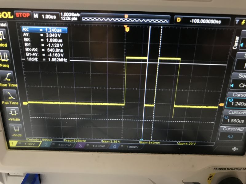 .
.
It is time to convert this to support WS2812B. We start by reading the catalogue note:
 .
.
First we have T0H - 0.4us. How many cycles will 0.4us be? 0.4us/25ns = 16.
Similarly, we count the remaining times. I came out with:
Code: C / C++
The WS2812B uses 8-bit RGB. In total we have 24 bits - 8 bits per channel. We will therefore need 24 objects of the rmt_item32_t structure.
Code: C / C++
I have added to the main loop:
Code: C / C++
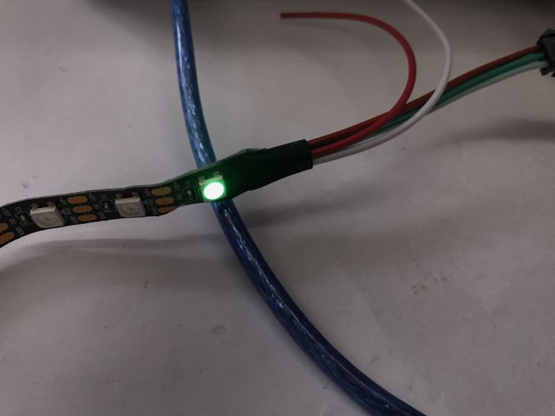
Flashes green... well, yes, but it's not an error. The format expected is GRB.
 .
.
 .
.
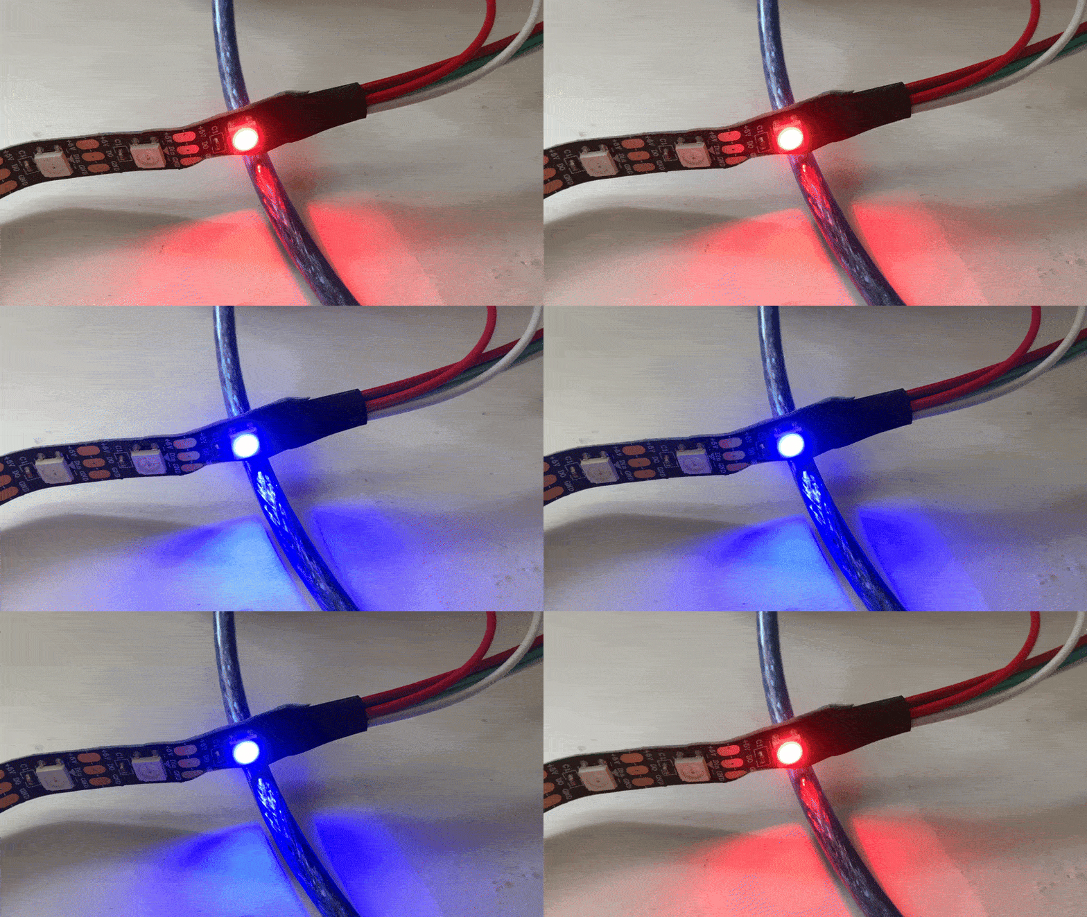
That's two colours now:
Code: C / C++
 .
.
The next step is to generalise the case for N pixels, or perhaps even better, for N bytes, as some bars are in RGBW format.
Code: C / C++
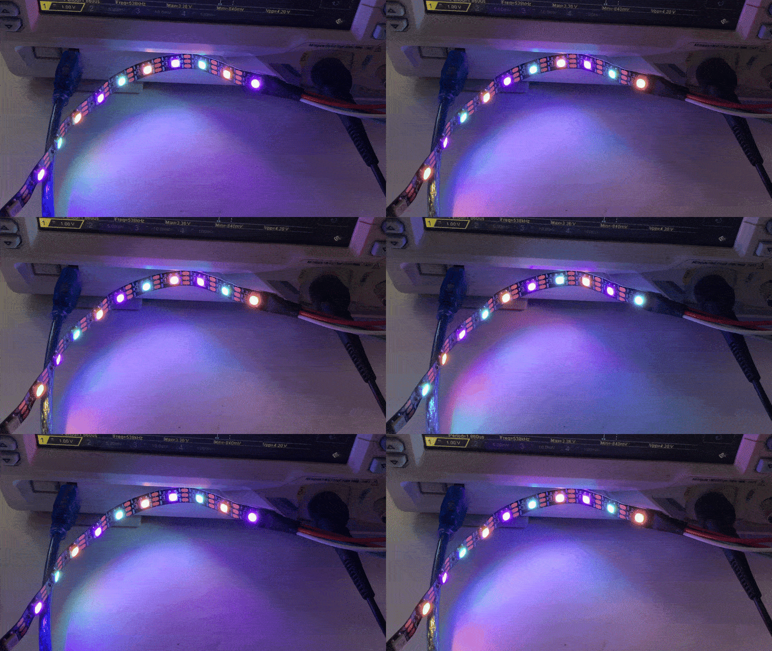
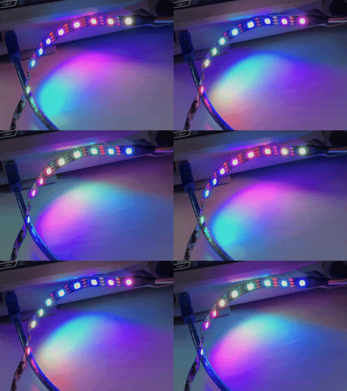
This way you can do effects where each pixel has a different colour:
Code: C / C++
Step is a counter which specifies the current frame of the animation.
 .
.
You could also use HSV and make a better animation as in WLED, but that's a bit beyond the scope of this topic:
Code: C / C++
The result:
 .
.
That's enough for today... The WS2812B control undoubtedly works, and you can always change the timings to suit a different type of LED if required. Handling an extra channel, white, won't be a problem either, because the code that converts bytes into RMT data doesn't "need to know" what the meaning of the bits is anyway.
I have made some simplifications in the theme, but I think this is not a problem and you can build your own WS2812 driver based on the solution shown here. I attach the full project in PlatformIO:


Comments