.
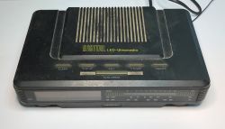
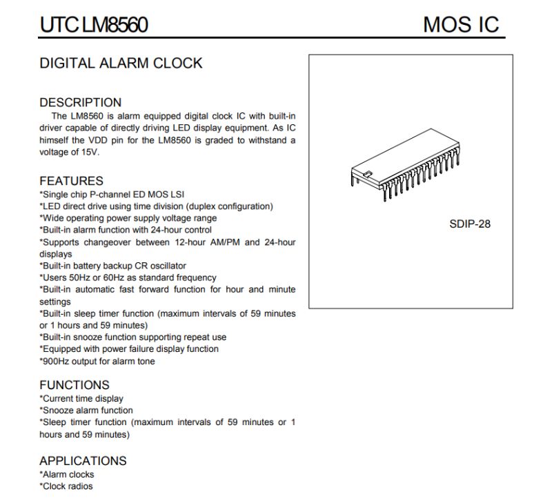
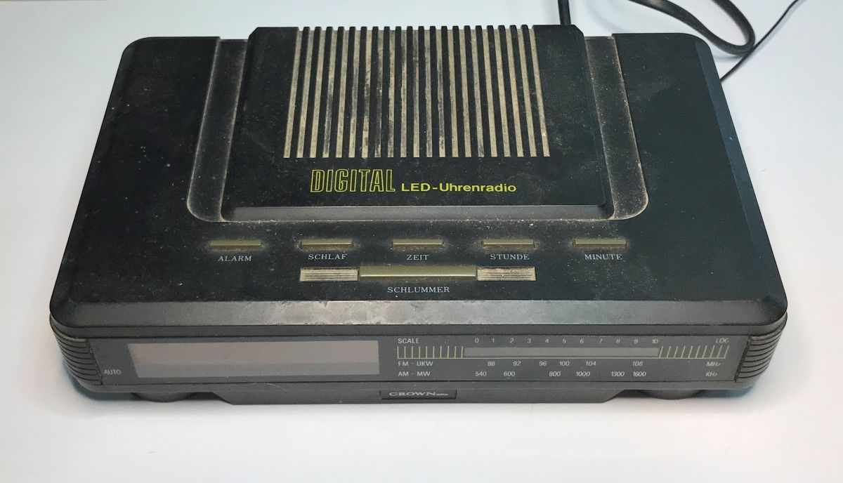
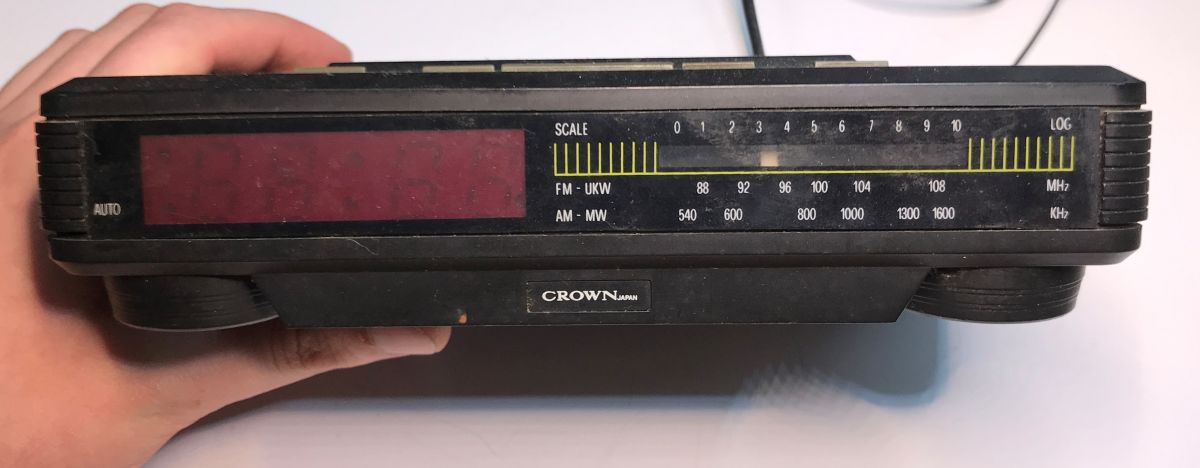
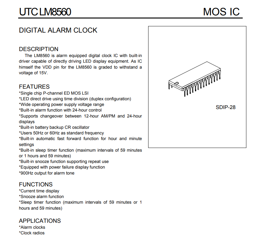
I would like to invite you to a presentation of the interior of an older Crown Japan radio alarm clock model CR-S9028, designated DIGITAL LED-Uhrenradio. The unit offers FM reception in the 88-108 MHz range and AM reception in the 540-1600 kHz range. It is equipped with an LED display showing the current time, an alarm clock function with snooze option, and battery back-up of the clock in case of mains power failure.

.
The inscriptions on the housing are in German. Uhrenradio, as you might guess, is a radio alarm clock. Schlummer is a snooze (postponement of the alarm). Zeit is the time, Stunde is the hour, Schlaf is sleep (this is probably the radio automatically switching off after a set time).
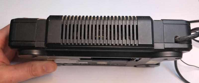
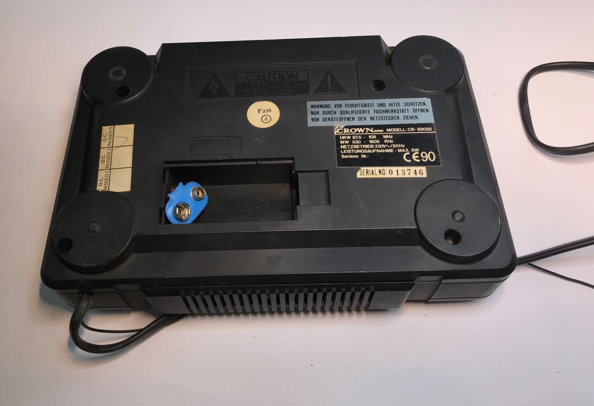
At the bottom is a space for a 9V battery, just for backup:

.
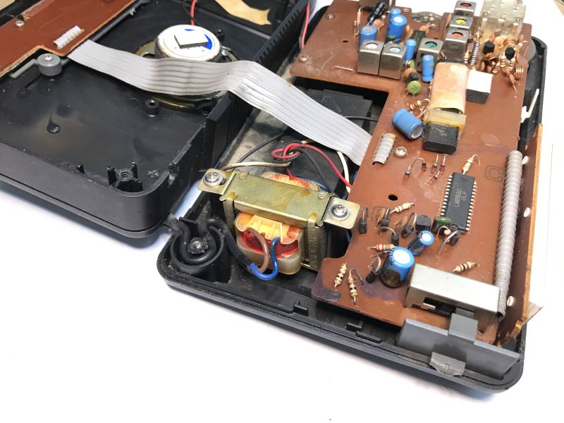
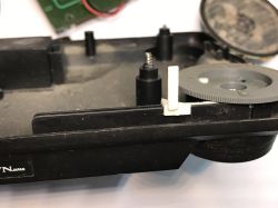
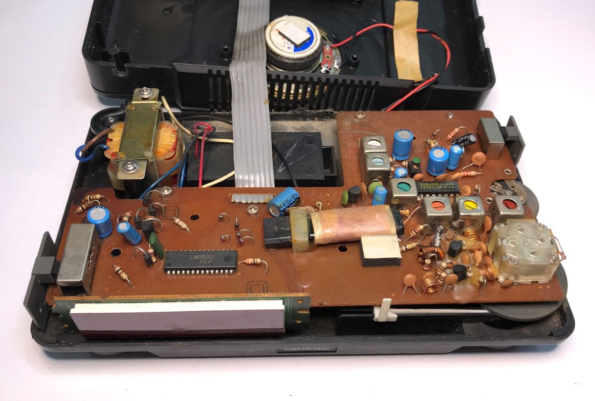
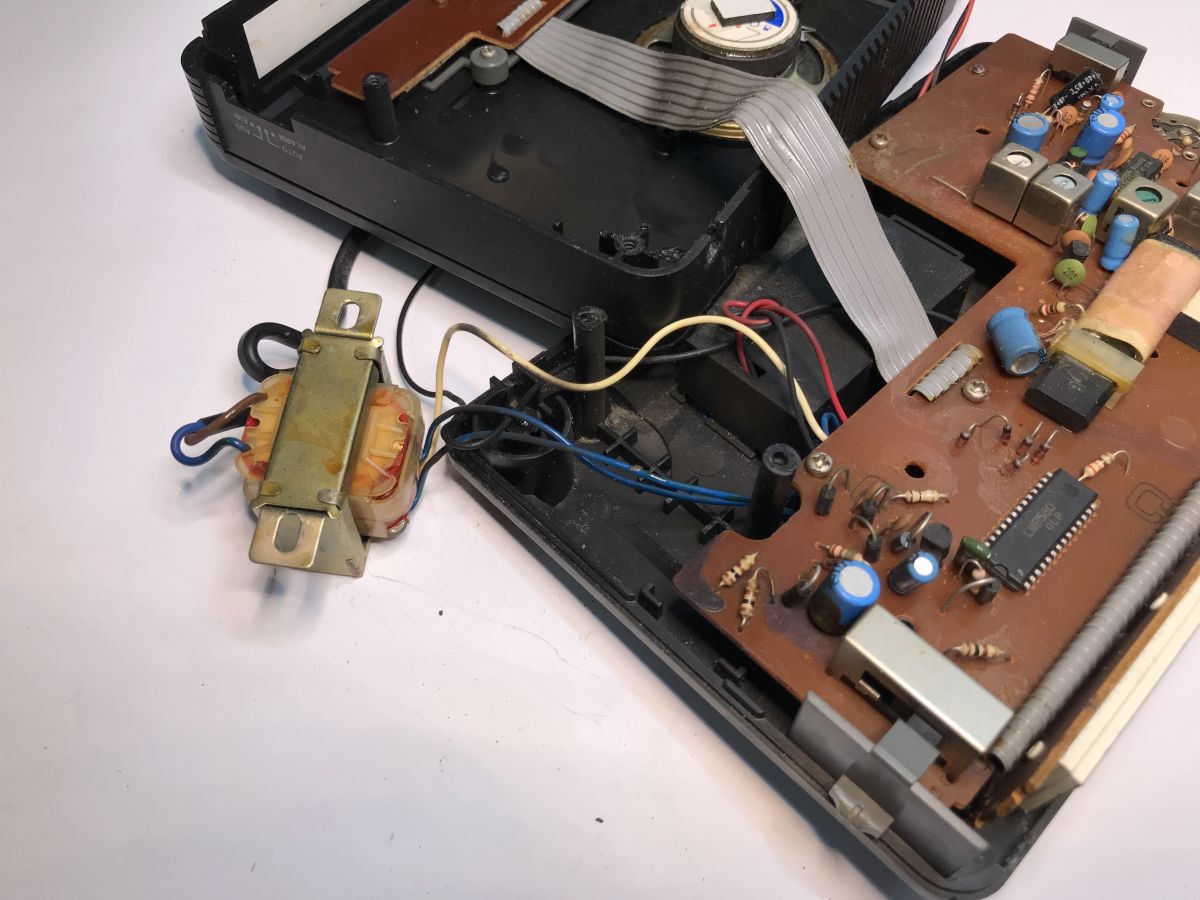
Let's take a look inside. The laminate inside is single sided and single layer. The assembly is fully threaded. The radio relies on a ferrite antenna and an adjustable capacitor and on coils protected with paraffin so as to prevent the coils from physically moving relative to each other.

.
The first thing we see is the display and alarm clock controller - the LM8560. About it in a moment. First, let's turn our attention to the power supply section - there is no switching power supply here, just a simple transformer. Heavier, but simpler to build.

.
.
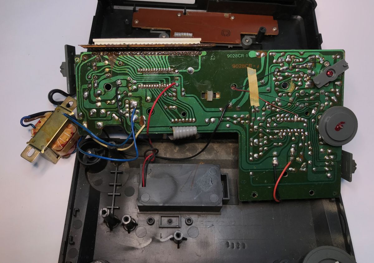
Now the underside of the PCB. It's been a long time since I've seen paths routed like this, is it handmade? Modern CAD programs don't run tracks like this. Here you can also see that the LM8560 directly controls the display.

.
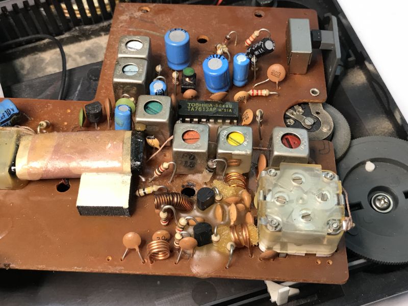
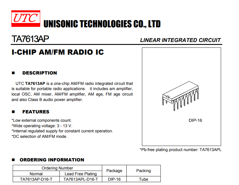
The radio itself is based on the TA7613AP:
.
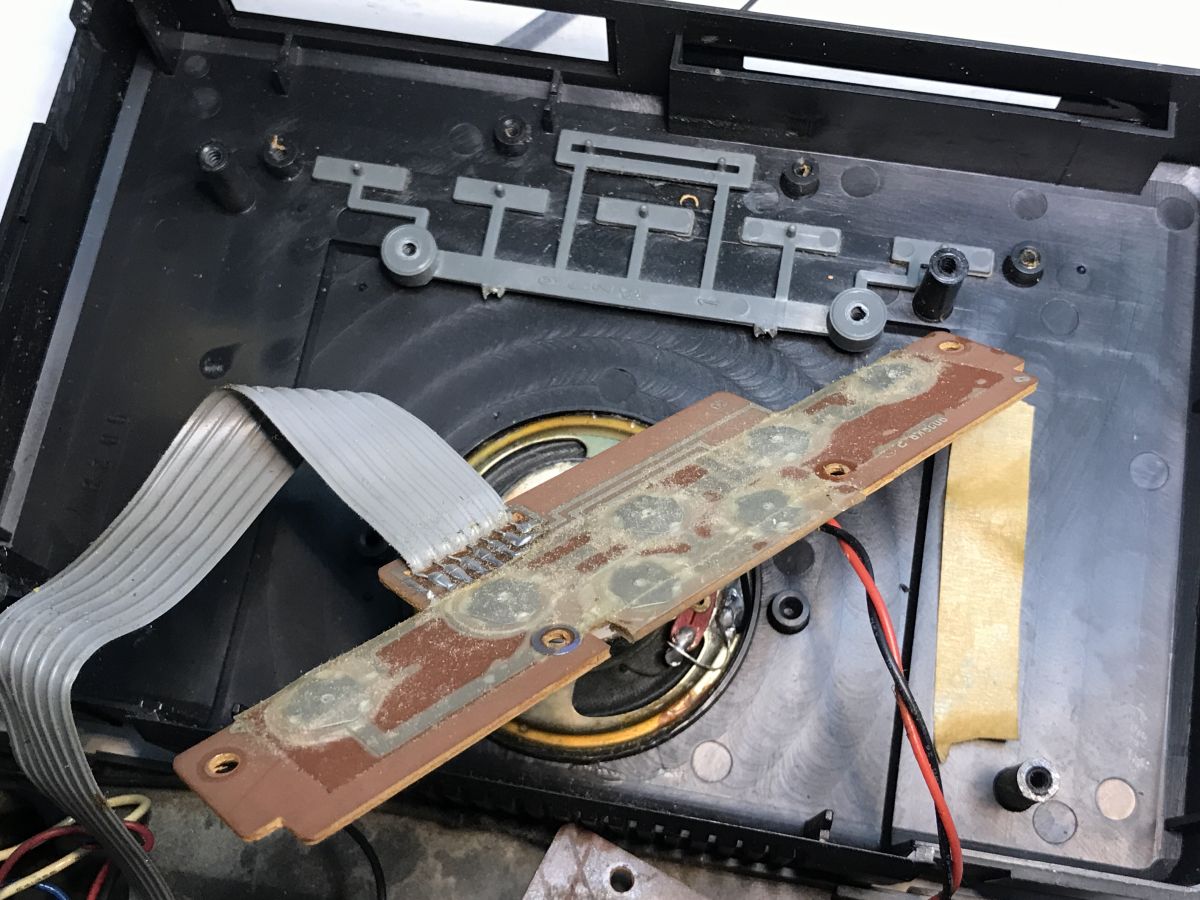
Basically that's it, the button board has no more electronics.

.
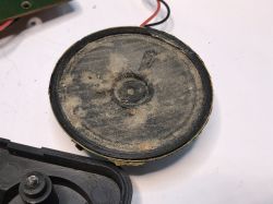
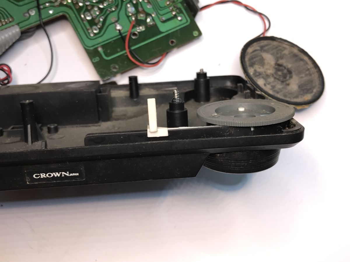
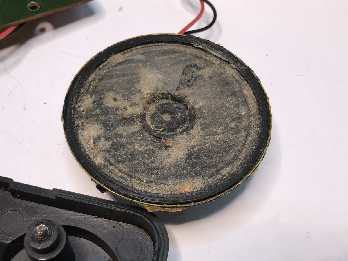
All that remains is the speaker:

.
Now it is time to look at the principle of operation. Here we have two circuits:
- LM8560 - a digital clock controller with built-in alarm, display, pushbutton operation and clocking from the mains via 50 or 60Hz
- TA7613AP - a single-chip AM/FM radio controller, including AM amplifier, oscillator, mixer, etc.
Don't confuse the LM8560 with a microcontroller - this chip was designed directly for alarm clocks:
.
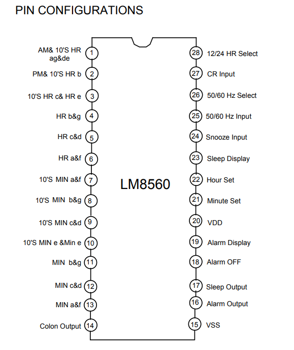
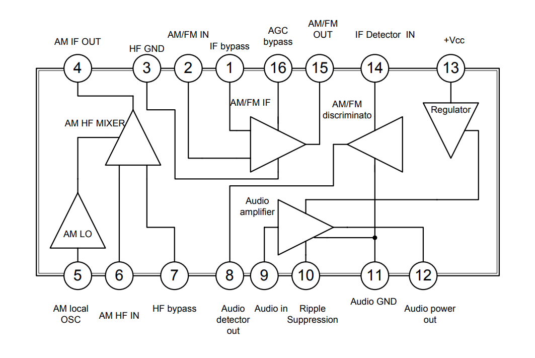
Pinouts:

.
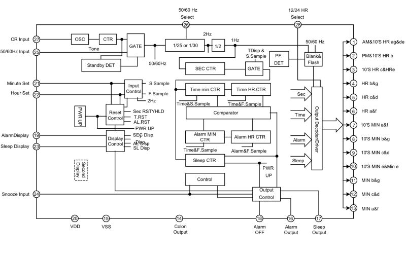
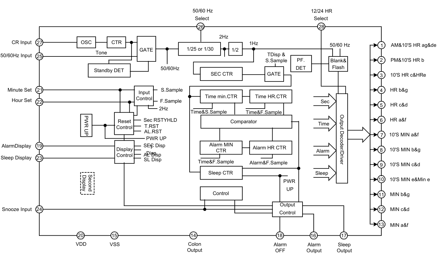
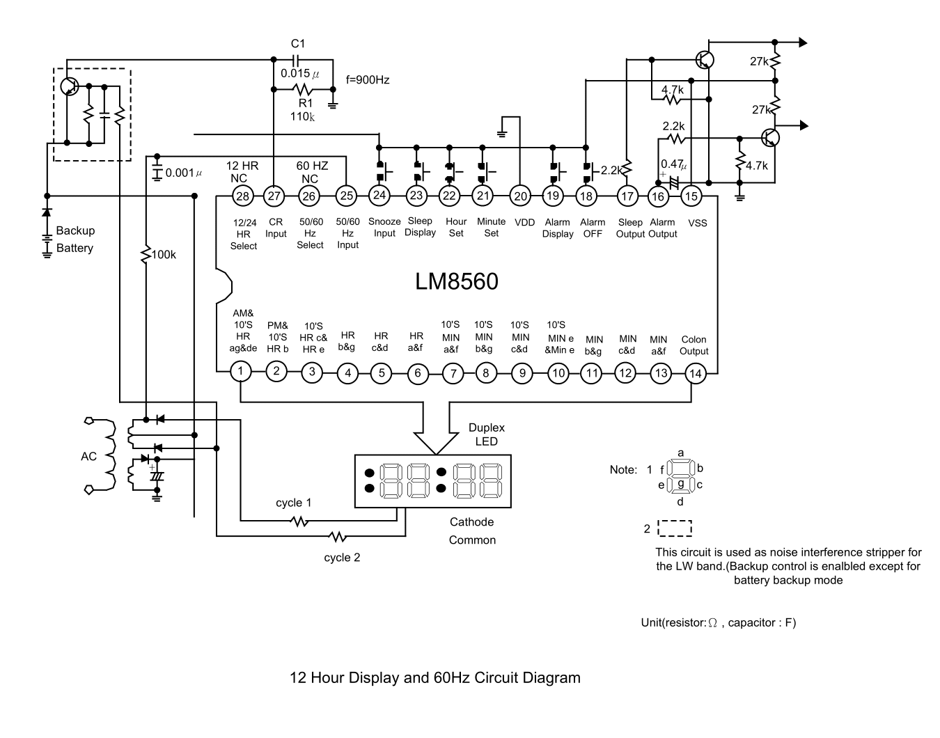
The internal design shows the pulse counting route well. We have two inputs - CR (oscillator) and 50/60Hz (from the transformer). These go to a gate which decides which pulses are counted. Then there is a divider for 50 or 60Hz (1/25 or 1/30) and then a divider in half so that we get 1Hz. This is then processed by the blocks from counting time, alarm and snooze...:
.
The LED multiplexing is solved in an interesting way. The display is with a common cathode, but the LM8560 only controls the segments. The common cathodes are controlled from... transformer, from the respective halves of the sine wave. The obvious consequence of this is that the display does not work when the whole thing is powered by battery only. Moreover, these common cathodes are two - and 14 segments each.

.
193650bb6 .
The schematics illustrate well how the clock is clocked from the mains, this is done by connecting from the transformer before the rectifying diode to the 50/60 Hz Input pin. Right next to it you can see the battery backup and the oscillator with resistor and capacitor (CR Input pin). The alarm output can switch the radio or buzzer.
This leaves the TA7613AP. As I've written before, it's basically a single chip AM/FM radio controller:

.

.
You don't even need an LM386 - there's already a Class B audio amplifier inside.
Summing up , there were essentially two separate sections inside - one was the simplest single-chip radio, all integrated into the TA7613AP, and the other was an IC designed for an alarm clock with a mains frequency-based countdown along with optional sustain on an RC resonator. I think I was most interested in this display multiplexed by that 50/60Hz from the mains.
Simple and functional, although I wonder what the stability of the mains frequency was like in the heyday of such products and whether the deviation of the time display grew rapidly.
Have you used this type of alarm clock, or do you still use one? My alarm clock in my primary school days was already a bit more technological, as it had an LCD....


Comments
They can, if one wishes - either by default, or with an additional plug-in.... https://github.com/mitxela/kicad-round-tracks [Read more]
Interesting plugin, somewhat along the lines of 'the exception proves the rule'. I don't normally see this type of track on modern projects. And you've reminded me that I was supposed to learn Kicad, but... [Read more]
That's how fast the deviation grew. I don't remember anymore, I associate something 20s but whether it was per day or per week.... My memory is not that good anymore. I remember that it had to be corrected... [Read more]
This stability probably varied according to use. In the 70s/80s it was rather poor and indeed such watches but also such "flip-flop" watches driven by a synchronous motor had to be corrected. By this... [Read more]
Today it is very good , the network holds stably 50Hz I have such a clock controlled by the frequency of the network in the microwave and practically does not need correction except for the time chang... [Read more]
In the case of the battery, there is no 50 Hz clocking and it is replaced by an internal 900 Hz oscillator with RC elements attached to pin 27 of the LM8560 chip. Without this oscillator the clock would... [Read more]
I have a radio alarm clock on the same chip, or perhaps on its twin brother (TMS3450) I'm not sure now. It's been going strong for a couple of years now; a few minutes a day* and I've been collecting to... [Read more]
By using SMD ICs and instead of a TTL 7490 chip a CMOS 4013 chip, such a generator can be significantly miniaturised. In the process, the LM78L05 stabiliser is eliminated. Pin 26 of the LM8560 chip is... [Read more]
. I had a similar radio alarm clock during communism in the '80s - from abroad I got it :] The deviations were b. large and you had to set it often, at least once a week. But I was catching on it even... [Read more]
. Unlikely, but if even that, just filter out with a suitably sized RC circuit these potential interferences on the 50Hz clocking input of the TMS3450 chip. So as not to significantly attenuate the 50Hz... [Read more]
. We have two 120Ω resistors in the cathode circuit of this display and the value can be increased slightly if required. [Read more]
. That's right, and I do this in any of my older devices (designed for 220V) that I care about that have an LED display or NIXIE powered by a non-stabilised voltage. I also add a small resistor in series... [Read more]
. SMD soldering doesn't really work well for me; making boards with such tiny tracks even more so. I used whatever circuits I had at hand. I've already checked the electrolytic capacitors... [Read more]
I had one. Timing accuracy on mains bearable. On battery backup time accuracy of 20%! It worked great for years when testing remote controls for a car. [Read more]
So I added two ceramic capacitors; 100 nF in parallel to the electrolyte in the power supply filter and 4.7 nF between the 50 Hz input (pin 25) and circuit ground (pin 15). And the alarm clock stopped... [Read more]
This happens because the 50Hz signal, apart from being a time pattern, is also used to multiplex the display. It is this Blank& Flash block in the internal block diagram of the IC. When this 50Hz... [Read more]