logo elektroda
logo elektroda
X
logo elektroda

Retro radio alarm clock with LED display - interior, construction, principle of operation

p.kaczmarek2 804 13
ADVERTISEMENT
Treść została przetłumaczona polish » english Zobacz oryginalną wersję tematu
📢 Listen (AI):
  • Retro radio alarm clock with LED display - interior, construction, principle of operation .
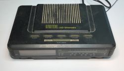
    I would like to invite you to a presentation of the interior of an older Crown Japan radio alarm clock model CR-S9028, designated DIGITAL LED-Uhrenradio. The unit offers FM reception in the 88-108 MHz range and AM reception in the 540-1600 kHz range. It is equipped with an LED display showing the current time, an alarm clock function with snooze option, and battery back-up of the clock in case of mains power failure.
    Retro radio alarm clock with LED display - interior, construction, principle of operation Retro radio alarm clock with LED display - interior, construction, principle of operation .
    The inscriptions on the housing are in German. Uhrenradio, as you might guess, is a radio alarm clock. Schlummer is a snooze (postponement of the alarm). Zeit is the time, Stunde is the hour, Schlaf is sleep (this is probably the radio automatically switching off after a set time).
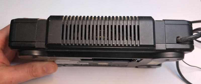
    At the bottom is a space for a 9V battery, just for backup:
    Retro radio alarm clock with LED display - interior, construction, principle of operation .
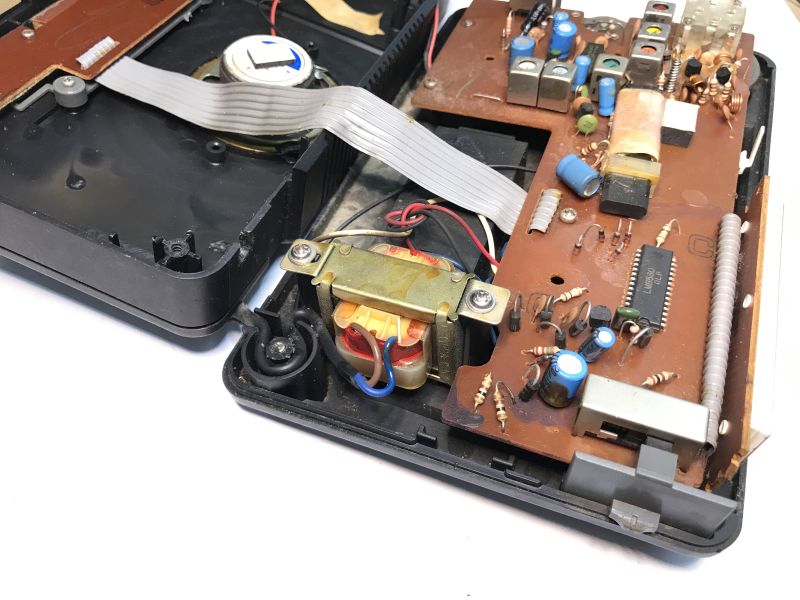
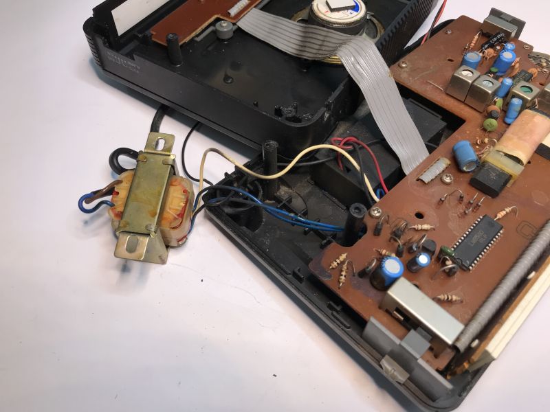
    Let's take a look inside. The laminate inside is single sided and single layer. The assembly is fully threaded. The radio relies on a ferrite antenna and an adjustable capacitor and on coils protected with paraffin so as to prevent the coils from physically moving relative to each other.
    Retro radio alarm clock with LED display - interior, construction, principle of operation .
    The first thing we see is the display and alarm clock controller - the LM8560. About it in a moment. First, let's turn our attention to the power supply section - there is no switching power supply here, just a simple transformer. Heavier, but simpler to build.
    Retro radio alarm clock with LED display - interior, construction, principle of operation .
    Retro radio alarm clock with LED display - interior, construction, principle of operation .
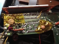
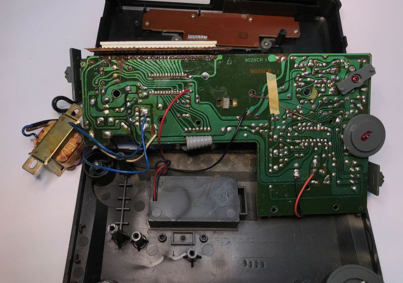
    Now the underside of the PCB. It's been a long time since I've seen paths routed like this, is it handmade? Modern CAD programs don't run tracks like this. Here you can also see that the LM8560 directly controls the display.
    Retro radio alarm clock with LED display - interior, construction, principle of operation .
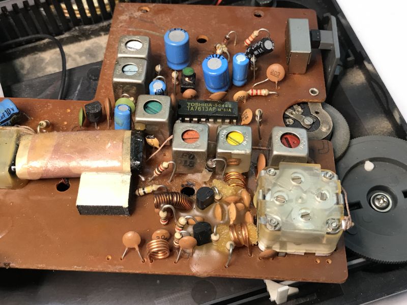
    The radio itself is based on the TA7613AP:
    Retro radio alarm clock with LED display - interior, construction, principle of operation .
    Basically that's it, the button board has no more electronics.
    Retro radio alarm clock with LED display - interior, construction, principle of operation .
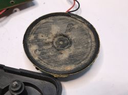
    All that remains is the speaker:
    Retro radio alarm clock with LED display - interior, construction, principle of operation Retro radio alarm clock with LED display - interior, construction, principle of operation View of the inside of the Crown Japan CR-S9028 clock radio, showing the main circuit board with LM8560 and TA7613AP chips, electronic components, and a ferrite antenna. .

    Now it is time to look at the principle of operation. Here we have two circuits:
    - LM8560 - a digital clock controller with built-in alarm, display, pushbutton operation and clocking from the mains via 50 or 60Hz
    - TA7613AP - a single-chip AM/FM radio controller, including AM amplifier, oscillator, mixer, etc.

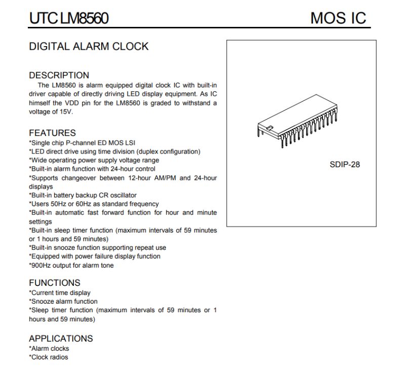
    Don't confuse the LM8560 with a microcontroller - this chip was designed directly for alarm clocks:
    Interior of the Crown Japan CR-S9028 clock radio showing the main circuit board, transformer, and installed integrated circuits. .
    Pinouts:
    Interior of an old Crown Japan CR-S9028 clock radio showing electronic components and a classic transformer. .
    The internal design shows the pulse counting route well. We have two inputs - CR (oscillator) and 50/60Hz (from the transformer). These go to a gate which decides which pulses are counted. Then there is a divider for 50 or 60Hz (1/25 or 1/30) and then a divider in half so that we get 1Hz. This is then processed by the blocks from counting time, alarm and snooze...:
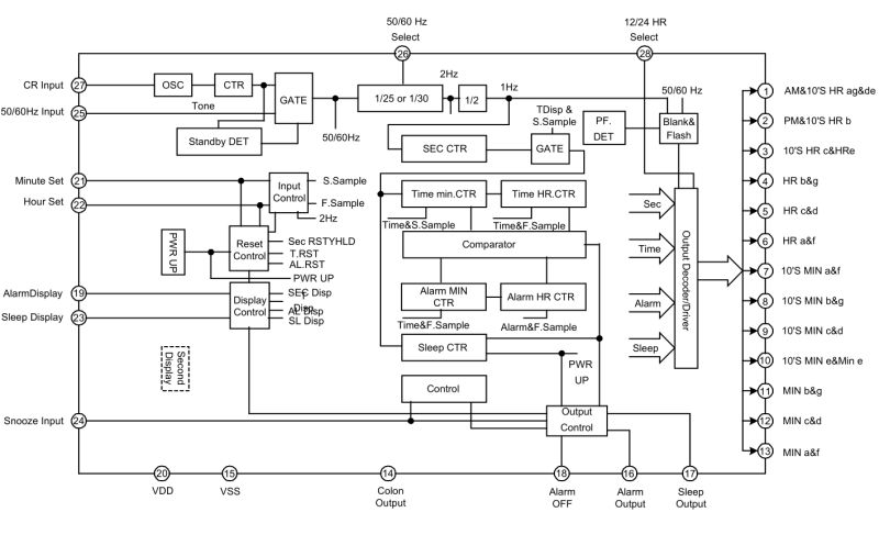
    Interior of the Crown Japan CR-S9028 clock radio showing circuit boards, transformer, and electronic components. .
    The LED multiplexing is solved in an interesting way. The display is with a common cathode, but the LM8560 only controls the segments. The common cathodes are controlled from... transformer, from the respective halves of the sine wave. The obvious consequence of this is that the display does not work when the whole thing is powered by battery only. Moreover, these common cathodes are two - and 14 segments each.
    View of the inside of an old Crown Japan CR-S9028 clock radio, showing the PCB and electronic components. .
    193650bb6 .
    The schematics illustrate well how the clock is clocked from the mains, this is done by connecting from the transformer before the rectifying diode to the 50/60 Hz Input pin. Right next to it you can see the battery backup and the oscillator with resistor and capacitor (CR Input pin). The alarm output can switch the radio or buzzer.

    This leaves the TA7613AP. As I've written before, it's basically a single chip AM/FM radio controller:
    Interior of the vintage Crown Japan CR-S9028 clock radio with visible PCB, transformer, ferrite antenna, speaker, and main electronic components. .
    The interior of the Crown Japan CR-S9028 clock radio, showing the main circuit board, electronic components, transformer, and speaker. .
    You don't even need an LM386 - there's already a Class B audio amplifier inside.

    Summing up , there were essentially two separate sections inside - one was the simplest single-chip radio, all integrated into the TA7613AP, and the other was an IC designed for an alarm clock with a mains frequency-based countdown along with optional sustain on an RC resonator. I think I was most interested in this display multiplexed by that 50/60Hz from the mains.
    Simple and functional, although I wonder what the stability of the mains frequency was like in the heyday of such products and whether the deviation of the time display grew rapidly.
    Have you used this type of alarm clock, or do you still use one? My alarm clock in my primary school days was already a bit more technological, as it had an LCD....

    Cool? Ranking DIY
    Helpful post? Buy me a coffee.
    About Author
    p.kaczmarek2
    Moderator Smart Home
    Offline 
    p.kaczmarek2 wrote 12030 posts with rating 10059, helped 577 times. Been with us since 2014 year.
  • ADVERTISEMENT
  • ADVERTISEMENT
  • #3 21597487
    p.kaczmarek2
    Moderator Smart Home
    Interesting plugin, somewhat along the lines of 'the exception proves the rule'. I don't normally see this type of track on modern projects. And you've reminded me that I was supposed to learn Kicad, but so far I've stuck with the free (limited) version of Eagle and I'm not complaining.

    That plugin has some limitations too, by the way:
    https://github.com/mitxela/kicad-round-tracks/commit/db1c740342c22c2b2c076a3a70164751cfff6005
    Helpful post? Buy me a coffee.
  • #4 21597559
    Ktoś_tam
    Level 39  
    p.kaczmarek2 wrote:
    .
    Simple and functional, although I wonder how in the heyday of such products was the stability of the frequency on the network and whether the deviation of the time indication grew rapidly.

    That's how fast the deviation grew. I don't remember anymore, I associate something 20s but whether it was per day or per week.... My memory is not that good anymore. I remember that it had to be corrected from time to time. As far as I remember the battery itself was even worse.
    By the way, I wonder what the deviation would be these days.
  • #5 21597580
    stachu_l
    Level 37  
    This stability probably varied according to use.
    In the 70s/80s it was rather poor and indeed such watches but also such "flip-flop" watches driven by a synchronous motor had to be corrected.
    By this time quartz resonators were already quite common so it was unlikely that they relied on the mains.
    From my dad's story - more to do with the 1950s/60s - a colleague involved in power production/distribution told my dad that after nights the power stations would spin a bit above 50Hz to make the daily number of grid sine waves match if the frequency was lower during the day. At that time, clocks driven by synchronous motors were quite common, and thus passed 24 hours a day, albeit a little slower during the energy peak and a little faster at night.
    Nowadays, I guess the frequency of the power grid in Europe is quite stable and controlled enough that the failure of a few units of Belchatow was recorded as a temporary drop in the frequency of the whole system.
  • ADVERTISEMENT
  • #6 21597742
    perkins1
    Level 12  
    >>21597559 Today it is very good , the network holds stably 50Hz I have such a clock controlled by the frequency of the network in the microwave and practically does not need correction except for the time change.
  • #7 21597825
    Citizen75
    Level 28  
    Ktoś_tam wrote:
    As far as I remember this has the battery itself been even worse.
    In the case of the battery, there is no 50 Hz clocking and it is replaced by an internal 900 Hz oscillator with RC elements attached to pin 27 of the LM8560 chip. Without this oscillator the clock would stop. Clock solutions are known with the LM8560 chip having a 3.2768 MHz quartz generator and the CD4060 and CD4013 chips.

    Close-up of an electronic clock circuit board with visible LM8560 integrated circuit and electronic components. .

    Radios built on this IC and its equivalents were quite popular about thirty years ago.
  • #8 21597903
    CHCl3
    Level 6  
    I have a radio alarm clock on the same chip, or perhaps on its twin brother (TMS3450) I'm not sure now. It's been going strong for a couple of years now; a few minutes a day* and I've been collecting to fit a quartz generator in it for about two years now. I have already made one such generator on a prototype board. On circuits 4060 and 7490 (with a 78L05 stabiliser) and a 4.096 MHz quartz. Unfortunately, due to the tightness, it was not possible to screw the case together after adding the generator board. I am currently waiting for the MM5369 chips ordered from China. One DIP8 chip, fewer components, then maybe such a generator can be squeezed into the case. As long as the circuits from Majfrends will work. The generator gives 60 Hz not 50 Hz so something needs to be changed in the clock IC connection.

    *I've read that this can be caused not so much by a deviation in the grid frequency as by the presence of "dirt" from inverters or converters. Actually, the neighbour has PV panels; maybe it's from that?
  • #9 21597984
    Citizen75
    Level 28  
    By using SMD ICs and instead of a TTL 7490 chip a CMOS 4013 chip, such a generator can be significantly miniaturised. In the process, the LM78L05 stabiliser is eliminated. Pin 26 of the LM8560 chip is used to select the 50/60Hz frequency.
  • #10 21598030
    misiek1111
    Level 36  
    Ktoś_tam wrote:
    I don't remember anymore, I associate something 20s but whether it was per day or per week...
    .
    I had a similar radio alarm clock during communism in the '80s - from abroad I got it :]
    The deviations were b. large and you had to set it often, at least once a week.
    But I was catching on it even the Voice of America on medium :]
  • ADVERTISEMENT
  • #11 21598061
    kris8888
    Level 39  
    CHCl3 wrote:
    I've read that this may be caused not so much by the deviation of the grid frequency as by the presence of , "sludge" from inverters or inverters. In fact the neighbour has PV panels; maybe it's from that?
    .
    Unlikely, but if even that, just filter out with a suitably sized RC circuit these potential interferences on the 50Hz clocking input of the TMS3450 chip. So as not to significantly attenuate the 50Hz but to cut out all the higher harmonics.

    The grid is currently very stable as far as the 50Hz fundamental frequency is concerned. If the watch is rushing a few minutes a day this is also more likely to indicate some sort of damage to the watch.
    p.kaczmarek2 wrote:
    The LED multiplexing is interestingly resolved. The display is with a common cathode, but the LM8560 only controls the segments. The common cathodes are controlled from... transformer, from the respective halves of the sine wave.
    .
    Unfortunately, this also has its drawbacks. This radio alarm clock was still designed for 220V AC on the mains. Now we have 230V and beyond. The LED display is therefore treated with a slightly higher voltage/current which can lead to segments burning out.
  • #12 21598325
    Citizen75
    Level 28  
    kris8888 wrote:
    This unfortunately also has its drawbacks. This radio alarm clock was still designed for 220V AC on the mains. Now we have 230V and more. The LED display is therefore treated with a slightly higher voltage/current which can lead to segment burnout.
    .
    We have two 120Ω resistors in the cathode circuit of this display and the value can be increased slightly if required.
  • #13 21598409
    kris8888
    Level 39  
    Citizen75 wrote:
    In the cathode circuit of this display we have two 120Ω resistors and you can increase their value slightly if needed.
    .
    That's right, and I do this in any of my older devices (designed for 220V) that I care about that have an LED display or NIXIE powered by a non-stabilised voltage.
    I also add a small resistor in series with the glow filaments in the VFD displays to extend their life.
    At my socket, unfortunately, it is 245 V all the time and sometimes a little more. I do not have a PV.
  • #14 21598629
    CHCl3
    Level 6  
    Citizen75 wrote:
    Using SMD ICs and instead of a TTL 7490 chip a CMOS 4013 chip such a generator can be significantly miniaturised. In the process, the LM78L05 stabiliser is eliminated. Pin no. 26 of the LM8560 chip is used to select the 50/60Hz frequency.
    .

    SMD soldering doesn't really work well for me; making boards with such tiny tracks even more so. I used whatever circuits I had at hand.


    kris8888 wrote:
    CHCl3 wrote:
    I have read that this may be caused not so much by the frequency deviation of the grid as by the presence of "dirt" from inverters or inverters. In fact the neighbour has PV panels; maybe it's from that?
    .
    Unlikely, but if even that, just filter out with a suitably sized RC circuit these potential interferences on the 50Hz clocking input of the TMS3450 circuit. So as not to significantly attenuate the 50Hz but to cut out all the higher harmonics.

    The grid is currently very stable as far as the 50Hz fundamental frequency is concerned. If the watch is rushing a few minutes a day this could also rather indicate some kind of damage to the watch.


    I've already checked the electrolytic capacitors (some that came out wrong on the measurements I replaced) the diodes and transistors (most in the radio part) too. Basically the only suspect remains the main circuit itself, and there's not much to check that.
    I'll try adding a filter of some sort; within a few days it should be apparent if it helps. If it doesn't, the package with the circuits from China is supposedly already in ,,transit country".
📢 Listen (AI):

Topic summary

The discussion centers on the Crown Japan radio alarm clock model CR-S9028, a vintage device featuring FM (88-108 MHz) and AM (540-1600 kHz) reception, an LED time display, alarm with snooze, and a 9V battery backup for clock retention during power outages. The device uses the LM8560 integrated circuit, common in radio clocks from about thirty years ago, which relies on a 3.2768 MHz quartz resonator and an internal 900 Hz oscillator for timekeeping when not synchronized to the mains frequency. The clock’s time stability depends on the power grid frequency, historically less stable but now maintained at a steady 50 Hz in Europe, reducing the need for frequent corrections. Deviations in timekeeping can arise from grid frequency fluctuations, interference from inverters or converters (e.g., photovoltaic systems), or component aging and damage. Modifications discussed include adding quartz oscillator generators (using chips like CD4060, CD4013, 7490, or MM5369) to improve accuracy, with considerations for frequency selection pins on the LM8560 to switch between 50/60 Hz operation. The LED display, originally designed for 220 V mains, may suffer from overvoltage due to modern 230-245 V supply levels, risking segment burnout; solutions include increasing series resistor values in the LED cathode circuits. The discussion also touches on the challenges of miniaturizing oscillator circuits using SMD components and the practical aspects of repairing and maintaining these vintage devices.
Summary generated by the language model.
ADVERTISEMENT