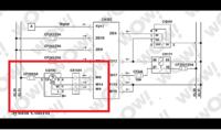
Dude Adam, it's so typical today, someone hasn't seen something, has no idea, writes nonsense, master, you are great, I bow, except that I did not claim to have seen a man-a alternator, although here the friend is wrong, because the man's alternator -and I saw, I even started the assembly line, from which brand new copies came out, but so what. Seeing is one thing, and helping to solve the problem is another. I wrote about checking the operation, I wrote that there may be an error in communication with the computer and, which often happens, after removing the error, the need to delete the error in the computer. A colleague knows that the error does not need to be deleted, this is a valuable tip, but the statement: "you will put the alternator and the installation in order" is general. Let's assume that the alternator marked in the diagram CG102 is OK (charges the batteries, after starting the engine there is 28V), C302 acts as a regulator, excitation current is supplied from M/3 to 4 (S) alt. , which regulates the voltage, the source of this current is 1 (W) fed to M/14 or 2 (L) fed to M/4. Battery Power 28V goes from B+ and this is the output from the windings after rectification by 6 diodes (bridge) 30-80A. Usually, additional diodes (bridge) of several amps are used to power the excitation winding, probably output 1(W) or 2(L). n
Signal A comes out of P2/17, most likely with information about the operation of the alternator.
Does anyone have a description of this schematic?


