logo elektroda
logo elektroda
X
logo elektroda

USB HID Connection: Exploring Stm32f103 Communication with PC & Unknown Device Detection

Pegasus 8277 21
ADVERTISEMENT
Treść została przetłumaczona polish » english Zobacz oryginalną wersję tematu
  • #1 11269219
    Pegasus
    Level 11  
    Hello,
           I have stm32f103 with a set of alarm + made USB pad (it detects as an unknown device, so in my opinion it works): d + hooked to PA_12 D- to PA_11. And now the problem is the lack of any example that would work in USB HID or as DFU. I wrote my own codes - they do not work, I used ready-made projects from STM - they do not work. Now, gentlemen, help me, because maybe my PC is going crazy and I do not want to cooperate with STM32, and I'm exhausted for hours and I can not see the problem, so if someone was struggling with a similar problem and solved it, I ask for a hint. Because my craze is taking so that a simple operation like USB communication would be unrealized on such a popular uC.

    Added after 2 [hours] 4 [ minutes]:

     Continuing the topic of not having a USB HID connection with stm32f103, connecting the same pad without stm32 results in the detection of an unknown device. At the moment of connecting the UC to the USB pad, nothing changes - I still have an unknown device. I think this is because the PC does not get an answer from the device both with and without connected uC. Now the question is, if the PC reads the pad itself as an unknown device, can it be copied in an attempt to communicate with the uC? Noting that the voltage measurement indicates that D + has a voltage of 1.84V and is this the correct result?
  • ADVERTISEMENT
  • #2 11269741
    figa_miga
    Level 19  
    I can be wrong there, but if you have HID, then the system is supposed to immediately detect it without fuss. The pull up should be 3.3V. if you have less then ... maybe a power problem ?. Do you have all the tensions attached to Prock?

    USB is not a simple matter at all, judging by the content I would not put up with communication from scratch.
    My advice is, instead of guessing it's better to create a layout according to the manufacturer's demo and give him the right input - he must move, or you do something wrong.
  • #3 11269856
    Pegasus
    Level 11  
    Thanks for the answer, it is already a step forward - I removed two protection diodes, which limited my voltage to D + to 1.84V in the pad and now I have 3.3V. Answering the question: I use the set of alarms and all the voltages there are tucked up, only there was no USB output, so I made them myself. Unfortunately, the fact that in the pad I have 3.3V on D +, I still do not change anything. And speaking of the right batch to stm32f103 is the whole knot to check the operation of my board on the tested program under this stm32, because at this point you are right that he guesses what may not work. In case I have a working and tested program under this stm (completely regardless of what it does, even one diode which gives the status on PC), I would rule out one position, because at this point everything looks good both shallow and program, and in theory everything works and in Lipton is already a practice.
  • #4 11269935
    piotrva
    VIP Meritorious for electroda.pl
    And what are your cables? It can show a photo how it looks because I bet on a hardware problem reading too long and unshielded cables in the USB interface === unknown device. If you have a usb socket, connect your adapter's pins to it and plug in the USB flash drive - how it works, just take on the stinging of stm and fighting programs that are not. You did not show us ...
  • #5 11269997
    Pegasus
    Level 11  
    Piotrva, thank you for advancing the idea from the pendrive, I will use it on Monday when I go to the USB socket and after the test I will be closer to success. The cable length is about 10 cm, only to be honest if this is the reason, is it even implemented in practice when connecting cables even below 5 cm (non-screen cables)? Continuing the topic of interference: the length of the cable should be added to the length of the path on the base of the USB on which there are also interference and at this point will get a distance of even less than 5 cm is difficult to do, or etching a plate of solid size there is no chance to use usb not placing it close to the uC? Returning to the topic of the stm32 batch, I use the examples stm - Custom_HID, it seems to me the most reliable and working program I can test. In the morning I will put a picture of my construction.
  • ADVERTISEMENT
  • #6 11270300
    figa_miga
    Level 19  
    If you had a problem with the soft / hardware, the system would buzz if the device was not working properly. And if it detects it as an unknown device, it means it's going through enumerations, but it's not really HID. What can you see in the manager?
  • ADVERTISEMENT
  • #7 11270303
    piotrva
    VIP Meritorious for electroda.pl
    You're not quite right ... Pendrive on the wrong cable reported as unknown ...
  • ADVERTISEMENT
  • #8 11270590
    Pegasus
    Level 11  
    I agree with both piotrva and figa_miga, because speaking about enumeration, the device certainly passes them (resulting in a result in the unknown device manager - Unknown device) only does not recognize it as HID which in turn is the result of interference. I hooked the usb pad to stm32 using centimeter cables and the result has not changed. The action of the pad will not be sure until it tests its pendrive what I will do on Monday (buy a usb socket).
  • #9 11270813
    gaskoin
    Level 38  
    It's interesting how the "pad" itself goes through enumeration.

    Pegasus wrote:
    Continuing the topic of not having a USB HID connection with stm32f103, connecting the same pad without stm32 results in the detection of an unknown device.


    Could you give a schematic of this "pad" or explain what it is? Providing your own terminology taken from space rather does not explain much to us.
  • #10 11270942
    ostrytomasz
    Level 24  
    Pegasus wrote:
    I agree with both piotrva and figa_miga, because speaking about enumeration, the device definitely passes them (resulting in a result in the manager with an unknown device - Unknown device) only does not recognize it as HID which in turn is the result of interference.


    You speculate too much - look at the details and not the name / message and compare. You will get an "unknown device" even when you connect the resistor 1k5 - at least on XP.
  • #11 11271140
    willyvmm
    Level 30  
    ostrytomasz wrote:

    You speculate too much - look at the details and not the name / message and compare. You will get an "unknown device" even when you connect the resistor 1k5 - at least to XP.


    That's how it works.
    Check in the device manager which VID and PID device receives.
    As 0000 and 0000 it means that there is no enumeration and there is NO | (correct) communication, only HUB has detected the device (resistor :D ).

    There may also be a wrong clock (PLL). USB has the right not to work as you drive them with HSI - too little accuracy and stability of the clock.

    Greetings.
  • #12 11271324
    piotrva
    VIP Meritorious for electroda.pl
    A PHOTO?
  • #13 11271328
    Pegasus
    Level 11  
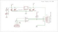
    Explaining what I call the washer, I put the diagram below:

    USB HID Connection: Exploring Stm32f103 Communication with PC & Unknown Device Detection

    I think that the pattern is correct. For sure I will do the plate again, because the reason for not working the correct device can be just cold February.
    Once again, I repeat that I use the Zl31ARM set (diagram and description of the set http://www.cyfronika.com.pl/uruchomieniowe/zl31arm.pdf), where after attaching a USB washer (diagram above), 3.3V and GND pins respectively pins for supplying the set, and D + and D- for pins PA12 and PA11, I expect that after uploading the program Custom_HID I will see that Windows has detected the HID device.
    Thanks for the information about the fact that Windows already detects 1.5k resistor as an unknown device. In the device manager there is information that the device has been stopped due to error code 43. At this point, I do not blame USB HID for a badly made washer. On Monday, I will make a new USB pad according to the diagram and I hope that I will get better results. I will deliver the results of my work on Monday, until then I am waiting for reservations regarding the scheme.

    Added after 30 [minutes]: < br />

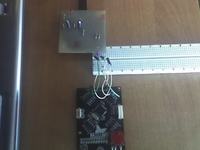
     I post the promised photo - the quality does not impress, but you can see that the pad and the set are connected (connections described in the previous post - checked repeatedly, both path leads on the pad and no damage on the cables). I connected both parts with / without contact plate and using shorter wires.

      USB HID Connection: Exploring Stm32f103 Communication with PC & Unknown Device Detection
  • Helpful post
    #14 11271921
    piotrva
    VIP Meritorious for electroda.pl
    First of all, call it a USB adapter or adapter because I do not know what it has to do with what we call a washer ;-)
    Secondly - these IMHO cables are too long for USB, besides it is not known (you can not see) how the paths on this adapter are run - and I remind - USB is quite capricious in these matters.
  • #15 11278288
    Pegasus
    Level 11  
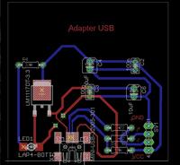
    I made the second tile and unfortunately, at this point, I consider this task to be unrealizable. The USB adapter is soldered well, but it can not even see correctly the flash drive applied directly through the socket for the USB adapter pins. I place a circuit diagram - brd file. (tile made according to the scheme placed in previous posts), I will just add that all the tracks are run on one layer (both red and white). To the advantages of the new stand, it should be added that the PC no longer sees the stand itself as an unknown device, so I think it's improving.
    USB HID Connection: Exploring Stm32f103 Communication with PC & Unknown Device Detection
    Now exhausted and with a lack of hope, he asks the question, is this what I'm going to (USB communication through the adapter) is a matter of defeat, is there hope?

    Added after 1 [hour] 11 [ minutes]:

     So if the USB adapter can not be made, is it okay to mount the socket on the PCB directly from the UC?
  • Helpful post
    #16 11279043
    ostrytomasz
    Level 24  
    Pegasus wrote:
    The USB adapter is soldered well, but it can not even see correctly the USB flash drive attached directly to the USB socket.


    See that in this situation you will have two pull-ups (on the adapter and in the pendrive) connected in parallel which is out of the scope of the specification. Disconnect at least for this pull-up test from the snap.

    Quote:
    I place a circuit diagram - brd file. (tile made according to the scheme in previous posts), I will just add that all tracks are run on one layer (both red as white - bottom)


    I am not saying that this is a problem, but by the way - the layout of the tile is disgusting, the capacitor C2 worse to put it probably did not give, with C3 also not better. Unless it has to work as an oscillator.

    Quote:

     The advantages of the new stand should be added by the fact that the PC can no longer see the stand itself as an unknown device, so it is probably an improvement.


    In my opinion, the deterioration (not counting that I do not know how vista / 7 behaves in such a situation).
  • #17 11280121
    Pegasus
    Level 11  
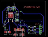
    OstryTomaszu thanks a lot to pay attention to such important fact as badly placed capacitors - I did not take this into account :( Of course, the capacitors should be as close as possible to the stabilizer legs, instead of banging over the entire tile (because the C2 placement is the pinnacle of mastery :) ). I will test the pendrive in the evening and write about the results. I have slightly improved the layout of the tile, I probably still do not see any obviousness and after etching another tile again something will not work, so I carefully listen to the next comments on the patch.
    USB HID Connection: Exploring Stm32f103 Communication with PC & Unknown Device Detection
  • Helpful post
    #18 11280926
    LordBlick
    VIP Meritorious for electroda.pl
    Pegasus wrote:
    that's why I am carefully listening to the next notes on patches
    Above make all USB data lines as short as possible and with equal lengths of paths - the easiest way is to insert the input and output sockets in parallel, ie LED1 up and turn the USB socket 90 ° to the right and slide to the left edge of the board. Also, move the slot to µ C to the left, so that there are still resistors in between. Generally, half of the used PCB area is enough.
  • Helpful post
    #19 11282230
    ostrytomasz
    Level 24  
    I do not want to criticize too much, but shallow how chaotic it is. I often have a lazy one myself and in the case of one-sided tiles I put the percentage of connections first, but here are only a few elements and it can be more sensibly arranged in a few moments.
    I looked at the schemes olimexu or ETT which I treated as a model - with the D + / D- lines there are additional 47p capacitors, if there are problems, maybe it is worth adding a place to them.
    In the attachment of the firmware I used with STM32F103C8 and CoIDE, CDC after minor modifications. It seems to me that it should be a comparatively "up" family. Quartz on ZL31ARM I see that it is the same.
  • #20 11283648
    Pegasus
    Level 11  
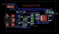
    Thanks OstryTomasz and LordBlick, of course, I agree that the previous tile was also chaotic. I used the LordBlick hint and placed the elements so that the D + and D- tracks were as short and as straight as possible. Capacitors placed as close as possible to the stabilizer pins. I have also added the recommended 47pF capacitors. Certainly the tile design is not perfect, but looking back and comparing with previous "creations" is better and at least in my opinion there is little hope :) on efficient action. Thank you for the criticism and for the exemplary program. I will carry out the tests in the evening after the tile is made (of course I will write about the results of my battle with USB). I will start making the plate at 14, so if there are any comments, I would like to shout, let n times you do not sell again :) .
    USB HID Connection: Exploring Stm32f103 Communication with PC & Unknown Device Detection
  • #21 11284318
    gaskoin
    Level 38  
    Then something is wrong with these paths (mainly with the power supply and the GND path).
  • #22 11285055
    Pegasus
    Level 11  
    Gentlemen, what joy came with me in the room when I tested the new USB adapter. The first tests inconspicuously indicated that once again I made a broken board - test pendrive = fail (I tested without pull-ups on D +, apparently the pendrive works only with 5V). The second test gave a bit of hope - the program of Ostry Thomas showed that the PC detected the device: miniscopev2c. Third test and full success :D , example program from STM - Custom HID worked. PC found a new HID device and USB HID Demonstrator showed my STM. For all those who have a USB problem, I put project files (EAGLE) maybe not a perfect but working USB STM32 adapter. Adding a few details I pay attention to the fact that I attached the attachment with cables without a screen about 10 cm long - thankfully, such length of cables and no screen is not a problem for USB communication. Thank you all for your help and most importantly, the right comments about the tile design.

Topic summary

The discussion revolves around the challenges faced in establishing a USB HID connection using the STM32F103 microcontroller. The user reports that their custom USB pad is detected as an unknown device by the PC, despite following various examples and guidelines. Responses highlight potential issues such as power supply problems, cable quality, and circuit design flaws. Suggestions include checking voltage levels, ensuring proper cable lengths, and reviewing the layout of the PCB to minimize interference. After multiple iterations and improvements to the design, the user successfully achieved USB HID recognition with the STM32F103 using the Custom HID example from STM, confirming that the device was detected correctly by the PC.
Summary generated by the language model.
ADVERTISEMENT