September 2025 Update:
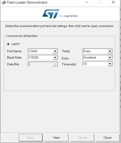
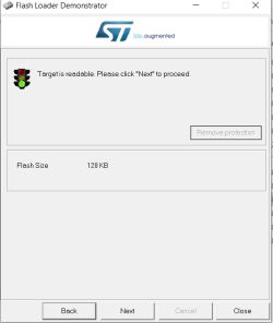
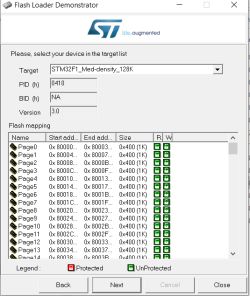
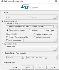
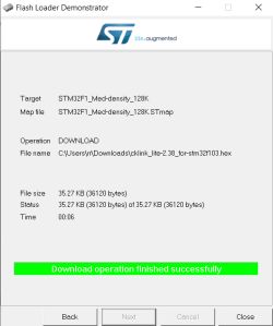
see here for details about converting STM32 over UART instead of J-Link (ie, J-Link not required) https://www.elektroda.com/rtvforum/topic4120455.html#21695356 (thanks @max4elektroda!)
see here for higher version converted CK-Link Lite firmware for STM32 https://www.elektroda.com/rtvforum/topic4120455.html#21554694
Here I'll document my journey with a cheap STM32F103C8T6 "blue pill" dev/hobby board bought from Ali Express. Despite the IC labelled as "STM32F103C8T6" the internal flash appears to be 128k instead of 64k making it more like an STM32F103CBT6. It seems this is not unexpected with STM32 fakes/clones.
The purpose of this purchase is to make a cheap C-SKY CK-Link / T-Head CPU debugger in the hope that I can access and dump the flash of C-SKY based chips like the WinnerMicro W800/W801/W806 which are C-SKY CK804FGT.
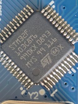
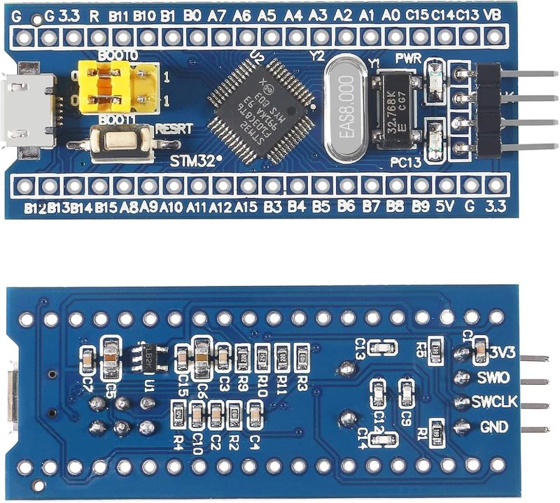
I bought 3 from the YouKeyi Store https://www.aliexpress.com/item/1005006999051681.html

Using cjacker's developments at https://github.com/cjacker/cklink-lite-fw-convertor we can convert the 'cklink_lite.hex' file that ships with the T-Head debug server so it will run on the STM32 after flashing. cjacker also supplies a binary that's already been converted https://github.com/cjacker/cklink-lite-fw-con.../blob/main/cklink_lite-2.36_for-stm32f103.hex and version 2.37, along with a Windows-compatible Python conversion script can be found in this PR https://github.com/cjacker/cklink-lite-fw-convertor/pull/1/files. I'll attach all files here for safe-keeping.
But how do we program the STM32? SWD - Serial Wire Debug!
Using one of these cheap clone J-Link programmer/debuggers we can flash the STM32 using J-Flash.

J-Flash can be downloaded from https://www.segger.com/products/debug-probes/j-link/technology/flash-download/
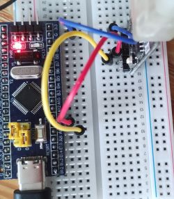
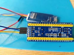
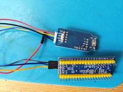
Connect like so
J-Link GND -> STM32 GND
J-Link SWDIO -> STM32 SWIO
J-Link SWCLK -> STM32 SWCLK
J-Link 3V3/VCC - <disconnected>
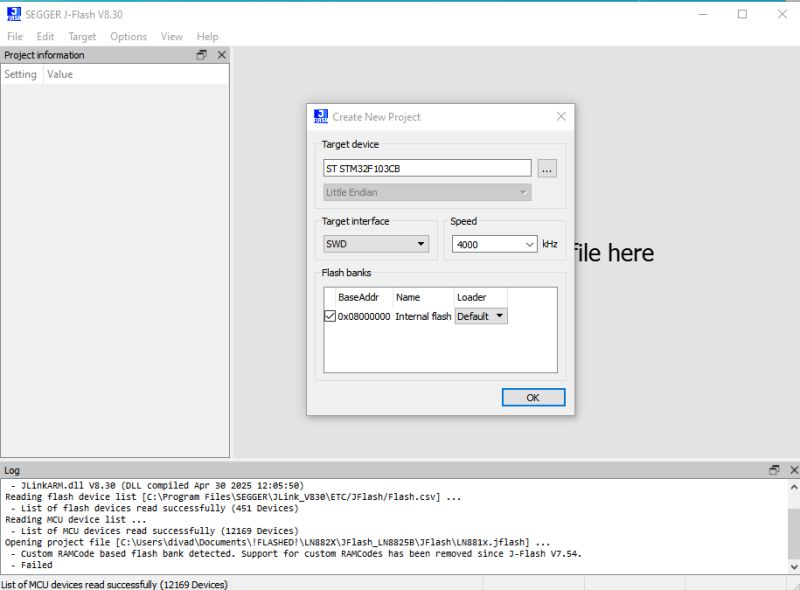
run J-Flash, make a new project and select "STM32F103CB" (128kb) from the target device list
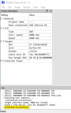
with both devices powered from their micro-USB ports 'Target' and 'Connect' in J-Flash menus should see the device connect successfully
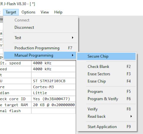
Now you can erase/write or read entire chip from the Target-> Manual Programming menu. First I read the Keil USB memory stick emulator demo thing that shipped with the STM32.
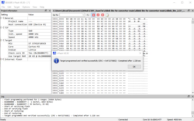
To flash cklink_lite-2.37_for-stm32f103.hex just drag the file into J-Flash window -> Erase Chip -> Program & Verify
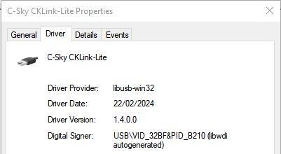
Power off the STM32 and re-plug it. If using Windows it should be detected as a C-Sky CKLink-Lite device
Now that this is done we need to engage with the T-Head debugging server so we can interface with C-SKY-based devices.
Register for and download the T-Head debug server from https://www.xrvm.cn/community/download?id=4380347564587814912 - I'll be demonstrating the Windows variant. I attach Windows and Linux downloads at the latest version at time of writing, as well as the debug user guide PDF.
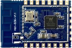
The CPU I'll be connecting to is the CK804 in a Hi-Link HLK-W806-KIT dev board, the same as explained here https://github.com/cjacker/opensource-toolcha...your-own-ck-link-lite-debugger-with-stm32f103
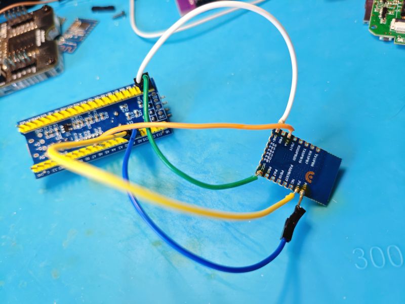
STM32 is connected to the HLK like so
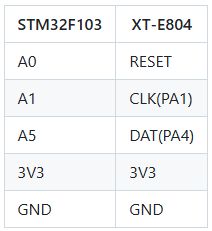
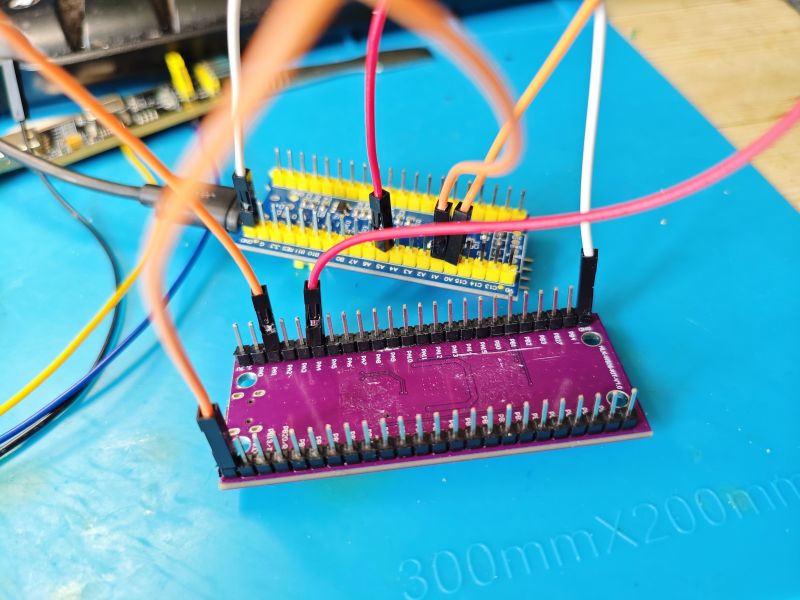
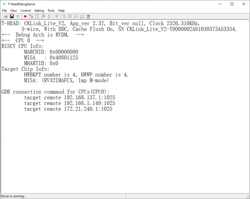
With power to STM32 and the W806, running the DebugServerConsole app should put the CPU into debug mode and show information about the CK-Link firmware version and the W806 CPU
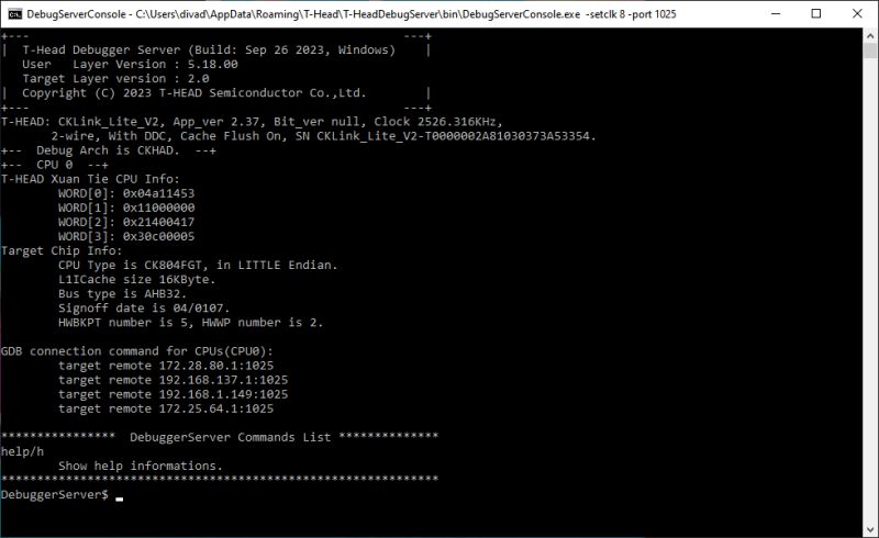
Extract the attached w806.elf file and put it into the \bin folder alongside the debug console executable - C:\Users\xxxx\AppData\Roaming\T-Head\T-HeadDebugServer\bin if installed to default location
Information about the elf file can be obtained with command flash -al w806.elf from the debug console
DebuggerServer$ flash -al w806.elf
For reference the entire flash command list is as follows
so we should be able to dump the W806 flash content with a command like this
those arguments meaning:
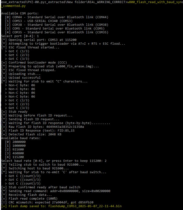
The dump appears to work. 1mb took 56 seconds.
The dump lands in \bin folder
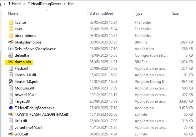
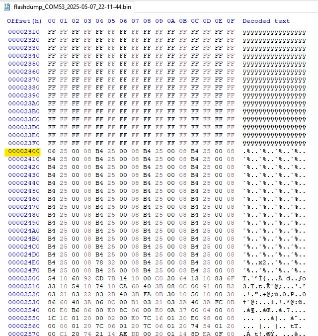
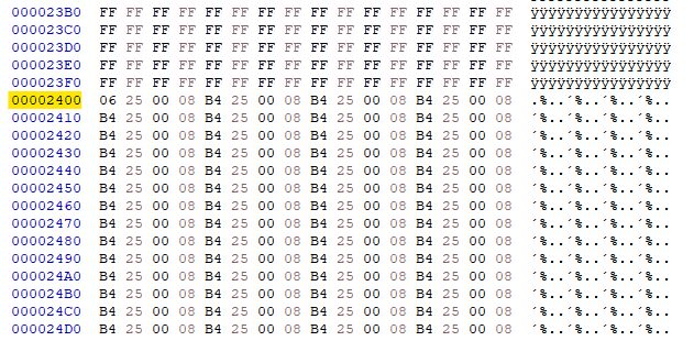
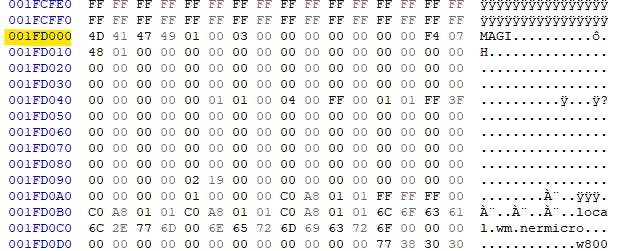
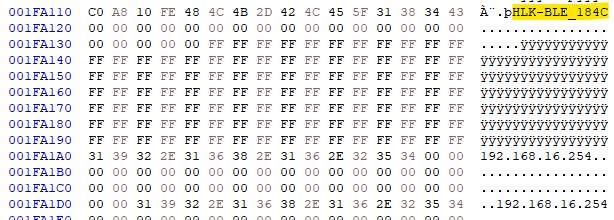
The resultant file appears to contain data and even some plain text from the W806 demo flashed using Upgrade Tools
Unfortunately flashing back as-is using command flash program -f blinkydump.bin -b -a 0x08000000 -al w806.elf does not appear to result in a bootable app, leaving the device waiting for an upload in the xmodem "CCCCCCCCCCC" mode

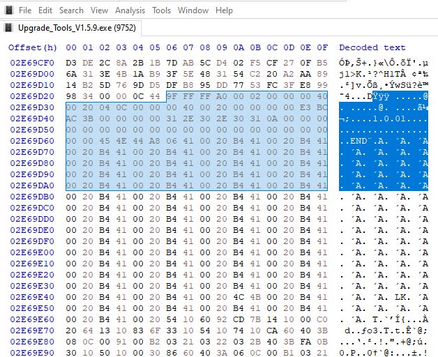
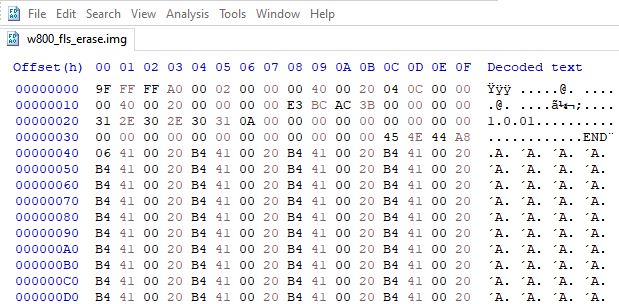
Also curious is that erasing flash even though 'successful', doesn't appear to actually zero the flash, a subsequent dump appears to be almost identical to one taken before the erase - this is also true if using wm_tool (wm_tool_1.0.4.exe -c com79 -eo all) to erase the W806 over UART - no empty flash, though it does appear to go into CCCCC mode after the erase, so maybe it's changing some byte to mark as empty?
debug console erase commands tried:
flash erase -a 0x08000000 -s 0x100000 -al w806.elf
flash erase -c -al w806.elf
Other observations:
COM port outputs this during read operations
and this with write
That's where I've got to right now. A working restore of the flash I think is the priority thing to work out. Unfortunately I do not have any C-Sky devices with their original firmware on to dump something new and interesting from a company like Tuya.
see here for details about converting STM32 over UART instead of J-Link (ie, J-Link not required) https://www.elektroda.com/rtvforum/topic4120455.html#21695356 (thanks @max4elektroda!)
see here for higher version converted CK-Link Lite firmware for STM32 https://www.elektroda.com/rtvforum/topic4120455.html#21554694
Here I'll document my journey with a cheap STM32F103C8T6 "blue pill" dev/hobby board bought from Ali Express. Despite the IC labelled as "STM32F103C8T6" the internal flash appears to be 128k instead of 64k making it more like an STM32F103CBT6. It seems this is not unexpected with STM32 fakes/clones.
The purpose of this purchase is to make a cheap C-SKY CK-Link / T-Head CPU debugger in the hope that I can access and dump the flash of C-SKY based chips like the WinnerMicro W800/W801/W806 which are C-SKY CK804FGT.


I bought 3 from the YouKeyi Store https://www.aliexpress.com/item/1005006999051681.html

Using cjacker's developments at https://github.com/cjacker/cklink-lite-fw-convertor we can convert the 'cklink_lite.hex' file that ships with the T-Head debug server so it will run on the STM32 after flashing. cjacker also supplies a binary that's already been converted https://github.com/cjacker/cklink-lite-fw-con.../blob/main/cklink_lite-2.36_for-stm32f103.hex and version 2.37, along with a Windows-compatible Python conversion script can be found in this PR https://github.com/cjacker/cklink-lite-fw-convertor/pull/1/files. I'll attach all files here for safe-keeping.
But how do we program the STM32? SWD - Serial Wire Debug!
Using one of these cheap clone J-Link programmer/debuggers we can flash the STM32 using J-Flash.

J-Flash can be downloaded from https://www.segger.com/products/debug-probes/j-link/technology/flash-download/
Connect like so
J-Link GND -> STM32 GND
J-Link SWDIO -> STM32 SWIO
J-Link SWCLK -> STM32 SWCLK
J-Link 3V3/VCC - <disconnected>


run J-Flash, make a new project and select "STM32F103CB" (128kb) from the target device list

with both devices powered from their micro-USB ports 'Target' and 'Connect' in J-Flash menus should see the device connect successfully

Now you can erase/write or read entire chip from the Target-> Manual Programming menu. First I read the Keil USB memory stick emulator demo thing that shipped with the STM32.

To flash cklink_lite-2.37_for-stm32f103.hex just drag the file into J-Flash window -> Erase Chip -> Program & Verify

Power off the STM32 and re-plug it. If using Windows it should be detected as a C-Sky CKLink-Lite device

Now that this is done we need to engage with the T-Head debugging server so we can interface with C-SKY-based devices.
Register for and download the T-Head debug server from https://www.xrvm.cn/community/download?id=4380347564587814912 - I'll be demonstrating the Windows variant. I attach Windows and Linux downloads at the latest version at time of writing, as well as the debug user guide PDF.
The CPU I'll be connecting to is the CK804 in a Hi-Link HLK-W806-KIT dev board, the same as explained here https://github.com/cjacker/opensource-toolcha...your-own-ck-link-lite-debugger-with-stm32f103
STM32 is connected to the HLK like so


With power to STM32 and the W806, running the DebugServerConsole app should put the CPU into debug mode and show information about the CK-Link firmware version and the W806 CPU
Code: Text

Extract the attached w806.elf file and put it into the \bin folder alongside the debug console executable - C:\Users\xxxx\AppData\Roaming\T-Head\T-HeadDebugServer\bin if installed to default location
Code: Text
Information about the elf file can be obtained with command flash -al w806.elf from the debug console
DebuggerServer$ flash -al w806.elf
Code: Text
For reference the entire flash command list is as follows
Code: Text
so we should be able to dump the W806 flash content with a command like this
Code: Text
those arguments meaning:
Code: Text
The dump appears to work. 1mb took 56 seconds.
Code: Text
The dump lands in \bin folder

The resultant file appears to contain data and even some plain text from the W806 demo flashed using Upgrade Tools
Unfortunately flashing back as-is using command flash program -f blinkydump.bin -b -a 0x08000000 -al w806.elf does not appear to result in a bootable app, leaving the device waiting for an upload in the xmodem "CCCCCCCCCCC" mode

Also curious is that erasing flash even though 'successful', doesn't appear to actually zero the flash, a subsequent dump appears to be almost identical to one taken before the erase - this is also true if using wm_tool (wm_tool_1.0.4.exe -c com79 -eo all) to erase the W806 over UART - no empty flash, though it does appear to go into CCCCC mode after the erase, so maybe it's changing some byte to mark as empty?
debug console erase commands tried:
flash erase -a 0x08000000 -s 0x100000 -al w806.elf
flash erase -c -al w806.elf
Other observations:
COM port outputs this during read operations
Code: Text
and this with write
Code: Text
That's where I've got to right now. A working restore of the flash I think is the priority thing to work out. Unfortunately I do not have any C-Sky devices with their original firmware on to dump something new and interesting from a company like Tuya.


