Translated from:
https://www.elektroda.pl/rtvforum/topic2774294.html
Welcome.
Beginner electronics dealing with microcontrollers from a very start are often very young and have limited knowledge of this field. Such an enthusiast who immediately wants to build some complex projects, may easily become frustrated and waste many hours if not even days on detecting the causes of the problems, and even then the results are likely to be far from perfect and costs generated can be high.
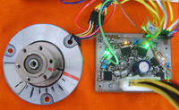
Therefore, I decided to prepare a very dedicated (educational) driver module (called driver) BLDC motor to:
1. to facilitate understanding of the principles of BLDC motor control,
2. to help a beginner avoid spending too much money on damaged electronic components, in particular, transistors.
The driver can also be used to control DC motors . It is based on one of the simplest schemes of this type of design. There is no logic to the problem of protecting the simultaneous inclusion of keys (transistors) of the top and bottom in a single phase:
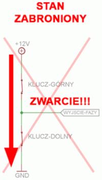
what very often happens to a novice programmer like the inverse power on.
In order to defend themselves any beginner can and should use software security features, which I call a fuse. Such a function should be called immediately after each commutation is completed and shall verify if the driver is not on in a manner that may causes a short circuit in one of three pairs of keys.
An example of such a function:
Code: C / C++
But as it happens in real life a beginner could make a mistake while typing the safety features, so if it is poorly written it cannot fulfill its function properly. And here came the idea to create a driver that at the stage of testing will meet the previously mentioned task, and by the way:
3. allowed to control BLDC motor via Back-EMF, Hall sensors and encoders.
4. allowed to experiment with different versions of the MOSFET and NPN gate control (additional elements in the form of capacitors or diodes).
Scheme
As I mentioned, this is one of the simplest schemes:
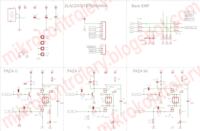
Important, however, are additional elements in the form of:
- Disconnecting jumpers on the testing time of the upper transistors from the bottom in one phase,
- LEDs,
- Test elements (symbolized by the capacitors).
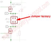
Jumpers
Jumpers are used primarily for disconnecting transistors in one phase, but also for an easy connection of the motor (I write about it later on in this post).
LEDs
autocad vs solidworks
rdson
channel bandwidth
ssh to specific port
progisp
duplexer vs diplexer
field application engineer
x5r vs x7r
rf choke
labview vs matlab
cpld vs fpga
timescale in verilog
dmips
mim capacitor
outage probabilityLEDs (when jumpers disconnected and motor is not connected) are used to observe which transistors are actually attached at a particular time. With this option, you can very easily and quickly check the reliability of the program.
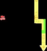
The figure above is the animation, but the server forum Elektroda.pl unfortunately removed animation.
You can see it here: http://mikrokontrolery.blogspot.com/2011/03/S...k-BLDC-driver-drajwer-schemat-plytka-pcb.html
Additional Capacitors
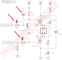
As I mentioned in point 4 driver contains extra elements to test a method for controlling gate MOSFET and NPN transistor base. In the diagram, they are marked as capacitors, but in their place, you can also insert a diode. In the standard version of the driver these elements are not installed:
Back-EMF
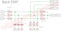
The driver is adapted to control the BLDC motor using a back-EMF signal that is, in cases where the motor has neither encoder nor Hall effect sensors, according to which the rotor position can be established. These elements are:
PCB
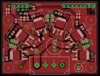
The PCB is made for educational purposes (mentioned earlier) and it has the unusual distribution of electronic components when compared to most drivers. The individual side of the plate as follows:
- top page:
- bottom page:
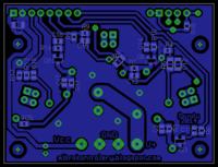
Board dimensions: 58.5 mm 44.5 mm.
PDF files can be found in the appendix at the end of this post.
Distribution of transistors is not accidental. They are arranged in an arc of two reasons:
- Simulating the rotation of the motor (LEDs illuminating sequentially)
- Heat Removal from the transistors.
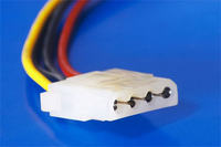
The driver is prepared to supply the computer with the AC adapter connector MOLEX
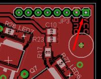
and to supply motor driver (part of the microcontroller) via the 5V voltage derived from the power supply connector JP3:
You do not need to fix the MOLEX socket - you can solder the wires by placing them in the top layer and bottom layer soldered on. Suitable markings are on the bottom side:

autocad vs solidworks
rdson
channel bandwidth
ssh to specific port
progisp
duplexer vs diplexer
field application engineer
x5r vs x7r
rf choke
labview vs matlab
cpld vs fpga
timescale in verilog
dmips
mim capacitor
outage probability
Vcc is the supply voltage part of the microcontroller (default 5V), and V + is the power MOSFET, which is the engine.
Tile is also prepared to attach to the contact plate, if you apply in nests godpins. However, I suggest that instead of goldpins use single slot.
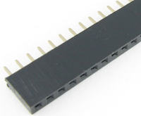
All w / in the connector must be soldered from the bottom.
Grommets
Tile has 24 vias, which must of course be soldered:
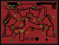
Modes driver
The driver can operate in two modes:
1. Test Mode - disconnected from the lower upper transistors,
2. Second mode - the upper and lower transistors connected.
On the PCB I designed three places combined and disconnects transistors phases:
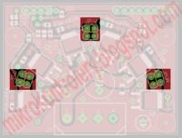
At this point, I designed the four holes in the pitch of 2.54 mm in order to be able to either solder wires or use goldpins row. I use the second approach:
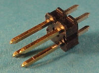
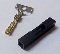
and use jumpers to connect the upper and lower transistors:
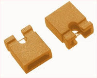
Test mode
This mode is disengaged from the lower upper transistors (jumper removed) and the disconnected engine. This mode allows you to observe the program working on the LEDs of each transistor.
In this way, without unnecessary risk you can fine-tune your program in such a way as not to cause the simultaneous opening of the two transistors, one phase (upper and lower).
Operation Mode
In this mode, the jumpers are in place, and the engine hooked to the respective phases:
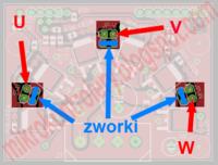
Movies
1. Motor control using Back-EMF signals
[youtube]https://www.youtube.com/watch?feature=player_embedded&v=_-Gfz2SXung
[/youtube]
2. Motor control with Hall sensors:
3. Monitoring the engine speed via RS-232 and the program Simplot:
[youtube]https://www.youtube.com/watch?feature=player_embedded&v=Jx35l8MFulI
[/youtube]
Homepage
Home course BLDC motor: BLDC motor - Table of Contents
Attachments:
https://www.elektroda.pl/rtvforum/topic2774294.html


