logo elektroda
logo elektroda
X
logo elektroda

Understanding Vce Voltage in BC337 Transistor Circuit Design: Analysis and Interpretation

ety 10194 17
ADVERTISEMENT
Treść została przetłumaczona polish » english Zobacz oryginalną wersję tematu
  • #1 16158179
    ety
    Level 14  
    When designing simple circuits with a transistor, should the voltage drop across the CE junction, i.e. the Vce voltage, be taken into account? If it is negligibly small, does it make no sense to include it in the calculations?

    For example, let there be a system in which 10 mA flows through the collector. Let the transistor be BC337.

    According to the note: http://www.onsemi.com/pub_link/Collateral/BC337-D.PDF

    How to read them correctly? Vce is on page 3, figure 2 and figure 4. Which graph are we interested in?
  • ADVERTISEMENT
  • #2 16158229
    Xantix
    Level 41  
    ety wrote:
    When designing simple circuits with a transistor, should the voltage drop across the CE junction, i.e. the Vce voltage, be taken into account?

    But what arrangements? Amplifier, key/switch or something else?
    ety wrote:
    If it is negligibly small, does it make no sense to include it in the calculations?

    Depends on what you calculate and for what needs?
    ety wrote:
    Vce is on page 3, figure 2 and figure 4. Which graph are we interested in?

    Generally, each of the graphs interests us and each has its own application.
  • #3 16158291
    ety
    Level 14  
    Let's assume that we control several LEDs from a microcontroller pin. The current efficiency of the microcontroller pin is small, so we use a transistor.
  • ADVERTISEMENT
  • #4 16158337
    Xantix
    Level 41  
    So the transistor as a key. Well, it seems to me that in this case the Vce voltage waveform itself does not interest us that much. The transistor works in two states in such a solution - it is either saturated or clogged.
    In the clogged state, as you know, Vce=VCC and Ic=0
    When in saturation, Vce is equal to Vcesat (assuming the transistor is fully saturated).
    Therefore, for the case you have given, we are interested in graph number 4 - because it tells us how the Vce voltage behaves when the transistor is in saturation.
    The value of Vcesat is important, among other things, because it determines the dissipation power dissipated in a saturated transistor (according to the formula Psat=Ic*Vcesat).
    P.S. And most importantly: in a bipolar transistor there is no such junction as a collector-emitter junction - there are only base-emitter and collector-base junctions .
  • ADVERTISEMENT
  • #5 16158436
    ety
    Level 14  
    Mhm ... Well, now I looked again at the construction of the npn transistor. The n layers are separated by a p layer, so electrically there is no direct connection (junction) between the collector and the emitter.

    As for the thread. So graph 4 assumes that the transistor is saturated and a larger current Ic cannot flow? I've always understood the saturation state more or less in this way: the base current is so large that the collector current can no longer increase, the transistor is not able to pass beta-times higher current. If so...

    Let's assume that we have some simplest arrangement, so completely pointless, as long as there is some basis for discussion.
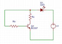
    Understanding Vce Voltage in BC337 Transistor Circuit Design: Analysis and Interpretation

    Let it be like this:

    Usup=12V - supply voltage
    Rb - resistor regulating the base current
    Rc - resistor for the LED (the question is whether it is needed?)

    Rc gives it so that there will be a voltage drop across it, unnecessary voltage. Suppose this is 12V, and on the diode let's assume Uled=2V. The voltage drop across Rc should be 10V. I just don't know if it would work without it too? We're assuming we're using this BC337 and the note I linked.

    We want the collector current Ic to be 20mA. In addition, the Ube voltage drop is assumed to be 0.7V (I don't see it in the note). I guess that's all.

    First we calculate Rb. In Fig.3 we have a gain graph. For Ic=20mA, the gain is about 180. So Ib=20mA/180=111uA. Let be Ib=0.1mA.

    Now from Ohm's law:
    Ub=12V-0.7V=11.3V
    Rb=Ub/Ib=11.3V/0.1mA=113k?

    Now we calculate Rc. Exactly. The voltage drop across Rc should be 10V. What about the drop between collector and emitter? Because there will be some?

    Without the drop, Uce (or Vce) would be:

    Rc=Uc/Ic=10V/20mA=500?

    Well cool. First of all, what about Uce?
    The second thing - what is with the graph you mentioned. This Fig.4. Because I don't think I'm satiated here, right? Collector current 20mA, and according to the note, the maximum is 800mA.
  • Helpful post
    #6 16158510
    Anonymous
    Level 1  
  • ADVERTISEMENT
  • Helpful post
    #7 16158525
    Xantix
    Level 41  
    ety wrote:
    The second thing - what is with the graph you mentioned. This Fig.4. Because I don't think I'm satiated here, right?

    There is. The graph is signed as Saturation Region - so it's definitely about saturation. And the saturation state itself does not mean that the maximum current flows through the collector.
    ety wrote:
    The saturation state has always been understood more or less like this: the base current is so large that the collector current can no longer increase,

    Wrong thinking - the collector current can increase, but not as a result of increasing the current Ib, but only as a result of a decrease in the resistance Rc.
    ety wrote:
    Rc gives it so that there will be a voltage drop across it, unnecessary voltage. Suppose this is 12V, and on the diode let's assume Uled=2V. The voltage drop across Rc should be 10V. I just don't know if it would work without it too?

    No - without a resistor, the diode will cook. Resistor Rc is needed to determine the assumed collector current at saturation.
    ety wrote:
    We want the collector current Ic to be 20mA. In addition, the Ube voltage drop is assumed to be 0.7V (I don't see it in the note). I guess that's all.

    First we calculate Rb. In Fig.3 we have a gain graph. For Ic=20mA, the gain is about 180. So Ib=20mA/180=111uA. Let be Ib=0.1mA.

    Now from Ohm's law:
    Ub=12V-0.7V=11.3V
    Rb=Ub/Ib=11.3V/0.1mA=113k?

    Now we calculate Rc. Exactly. The voltage drop across Rc should be 10V. What about the drop between collector and emitter? Because there will be some?

    Without the drop, Uce (or Vce) would be:

    Rc=Uc/Ic=10V/20mA=500?

    Wrong. You count it as if the transistor were an amplifier. And in this setup, it's the key. So it works two-way. If you want to put the transistor in saturation, you use the rule Ib>0.1 Ic and for this dependence you set the resistor Rb. Assuming Ic=20 mA, you must add a resistor Rb so that the current Ib is more than 2 mA.
    If Vcesat is negligibly small compared to Vcc then for practical and undemanding calculations you can neglect it. However, if the result is to be very precise then you must take Vcesat into account regardless of its value.
  • #8 16158535
    ety
    Level 14  
    Xantix wrote:

    ety wrote:
    The second thing - what is with the graph you mentioned. This Fig.4. Because I don't think I'm satiated here, right?

    There is. The graph is signed as Saturation Region - so it definitely concerns the state of saturation. And the saturation state itself does not mean that the maximum current flows through the collector.


    No no. What I meant was that in this example of mine the transistor is not in saturation. Graph - known to be about saturation.
  • #9 16158545
    Anonymous
    Level 1  
  • #10 16158671
    ety
    Level 14  
    trymer01 wrote:
    For the saturation state, we do not look at the beta value, but assume a much lower beta - according to the manufacturer's recommendations - p., the "Collector Emitter Saturation Voltage" table is given at Ic/Ib=10. From practice it is known that this value can be increased to 20 (Vcesat will increase slightly).


    Where is a beta of 10 stated? You mean we should start a small beta? Was it a mistake and meant beta 100? Because maybe I'm blind, but I don't see 10 in the table ... Also not on the hFE chart. I must be missing something :D

    trymer01 wrote:
    Figure 5 - Vcesat=f(Ic), with Ic/Ib=10 - do you understand that?
    From this graph, Vcesat= about 0.05V, so Ic=(Vcc-Vled-Vcesat)/Rc=19.9mA. this difference of 0.1 mA matters to you? - because it's 0.5%, and the resistor has a tolerance of 5%. And even so, include the Vcesat value in your calculations.


    Well, now I think I see what it was. And I know where to read Vce. I know, I know, the so-called pharmacy difference.

    trymer01 wrote:
    This graph shows what current Ib needs to be applied to the base to drive the transistor into saturation (to get low, little changing Vcesat) - for different Ic. There you can see that the larger Ic, the smaller the "beta" and the more difficult it is to bring the transistor into saturation.


    So if I want to put the transistor in saturation at Ic=20mA, I can safely calculate everything for the base current of 1mA? That's how I understand +/- from the graph. Fig4.

    Xantix wrote:
    No - without a resistor, the diode will cook. Resistor Rc is needed to set the assumed collector current at saturation.


    I see. I thought that we are able to control the "working point" of the transistor (because I think that's what it's called) so that without the additional resistance Rc the current would be 20mA.

    Xantix wrote:
    If you want to put the transistor in saturation, you use the rule Ib>0.1 Ic and for this dependence you set the resistor Rb. Assuming Ic=20 mA, you must add a resistor Rb so that the current Ib is more than 2 mA.


    I know it's a stupid question, but where did this rule come from? Is it just an "engineering formula" for quick estimation? As for wavelength 300/f[MHz]=lambda [m].

    trymer01 wrote:
    No - the current flowing through the saturated transistor depends only on Vcc and Robc.


    It's just supposed to be a switch, i.e. there is either a clogged state (LED is off) or a saturation state (LED is on). I'm beginning to understand. What about the active state between these two states. Theoretically, if instead of the Rb resistor, put a potentiometer? So theoretical - where would the resistance start at the calculated Rb and increase as it spins, reducing the base current? Then we would move from saturation to clogging (through active state) relatively smoothly?
  • #11 16158685
    Xantix
    Level 41  
    ety wrote:
    I know it's a stupid question, but where did this rule come from? Is it just an "engineering formula" for quick estimation?

    Apparently it was established empirically - in any case, I always followed this rule in calculations and never had problems with incomplete saturation of the transistor.
    ety wrote:
    Theoretically, if instead of the Rb resistor, put a potentiometer? So theoretical - where would the resistance start at the calculated Rb and increase as it spins, reducing the base current? Then we would move from saturation to clogging (through active state) relatively smoothly?

    So then the transistor would work in active state.
  • #12 16158724
    Anonymous
    Level 1  
  • #13 16158804
    ety
    Level 14  
    Thank you very much. I haven't burned any transistor yet, and as you can see, I don't know everything yet :) Good thing I asked Vce about it.

    trymer01 wrote:
    You could say.
    The manufacturer of the BC337 guarantees that Vcesat will be at the given value @ic with the given Ic/Ib. In other conditions - it is not known, because the transistor is not equal to the transistor.
    Read:
    https://www.elektroda.pl/rtvforum/topic2770848.html#13381877
    https://www.elektroda.pl/rtvforum/topic2617821.html#12578613
    https://www.elektroda.pl/rtvforum/topic3240162.html#15889806


    I understand that in theory such a system as I proposed (well, I should move the LED) would work. In practice, however, for some more serious applications, the base could be susceptible to interference. With a larger base current, a drop in this current would not significantly affect the collector current. Of course, within certain limits. That's how I understand it, from the linked materials.

    trymer01 wrote:
    ety wrote:
    What about the active state between these two states. Theoretically, if instead of the Rb resistor, put a potentiometer? So theoretical - where would the resistance start at the calculated Rb and increase as it spins, reducing the base current? Then we would move from saturation to clogging (through active state) relatively smoothly?

    Yes, but such control of the transistor is not stable and changes in conditions (changes in external temperature, transistor heating, load change, power supply) can cause the transition from the shallow saturation state to the active state (and this will either destroy the transistor or cause the load to malfunction), or going from the active state to the saturation state.


    OK, but what about audio amplifiers with adjustable gain?

    Of course, I understand that when controlling via a transistor on the on/off basis, we follow slightly different rules. We are supposed to have stable two states ON and OFF. Clogging and saturation. We don't seem to be interested in the active state.
  • #14 16158819
    Xantix
    Level 41  
    ety wrote:
    OK, but what about audio amplifiers with adjustable gain?

    Well, amplifiers with adjustable gain are rather much more complicated to build.
    And as for such a simple amplifier with one transistor, more complex transistor polarization systems are used, designed to ensure the stability of the amplifier parameters regardless of fluctuations in external factors.
    ety wrote:
    Of course, I understand that when controlling via a transistor on the on/off basis, we follow slightly different rules. We are supposed to have stable two states ON and OFF. Clogging and saturation. We don't seem to be interested in the active state.

    Basically that's how it is.
  • #15 16159492
    Anonymous
    Level 1  
  • #16 16160042
    ety
    Level 14  
    trymer01 wrote:
    when the frequency is high you need different.


    I mean, they strive for the same thing (deep saturation), but probably in a slightly different way?
  • #17 16160063
    Xantix
    Level 41  
    No - then the transistor is not entered into deep saturation, because it takes the transistor a relatively long time to get out of this state (compared to the frequency of the signal), which would disturb the switching of the transistor. Therefore, in such a case, one should try to keep the saturation state as shallow as possible. What exactly? And it depends on many factors...
  • #18 21044399
    mahdh
    Level 1  

    The Vce should be taken into account when designing circuits. It is representing the saturation voltage when the transistor is in its active region, conducting current. In most cases, this voltage drop is not negligible, and it can have a significant impact on the performance of the circuit.

Topic summary

The discussion centers on the importance of considering the Vce voltage drop in BC337 transistor circuit design, particularly when using the transistor as a switch to control LEDs from a microcontroller. Participants clarify that while Vce is often small, it should not be neglected in precise calculations, especially in saturation conditions. The BC337 operates in two states: saturation and cutoff, with Vcesat being critical for power dissipation calculations. The conversation also touches on the necessity of base current (Ib) being significantly higher than the collector current (Ic) to ensure saturation, and the implications of circuit design choices on performance and stability.
Summary generated by the language model.
ADVERTISEMENT