Czy wolisz polską wersję strony elektroda?
Nie, dziękuję Przekieruj mnie tam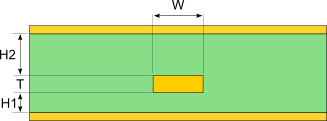
| Trace Thickness | T | ||
| Substrate Height | H1 | ||
| Substrate Height | H2 | ||
| Trace Width | W | ||
| Substrate Dielectric | Er |
![Z_{0,AS}=\frac{1}{\sqrt{\varepsilon_r}}\left [ Z_{0,SS}(\varepsilon_r=1, b=h_1+h_2+t)-\Delta Z_{0,air} \right ]](https://obrazki.elektroda.pl/1870558300_1718711415.webp) Eq. 1
Eq. 1
where:
Z0,SS is the symmetric stripline impedance computed according to Eq. 1 or Eq. 3 of the Symmetric Stripline Impedance tool, providing the following input values: Ɛr=1, b=h1+h2+t. Z0,SS is the impedance with air as the dielectric and having total thickness, b, equal to h1+h2+t.
ΔZ0,air is given by the following equation:
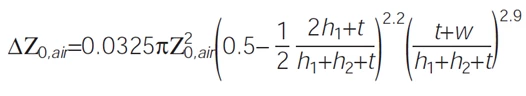 Eq. 2
Eq. 2
Where h1 is the distance between the signal line and the lower reference plane, h2 is the distance between the signal line and the upper reference plane, and Z0,air is given by:
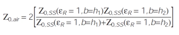 Eq. 3
Eq. 3
Z0,SS is the symmetric stripline impedance computed according to Eq. 1 or Eq. 3 of the Symmetric Stripline Impedance tool, providing, in turn, the following input values:


