Czy wolisz polską wersję strony elektroda?
Nie, dziękuję Przekieruj mnie tam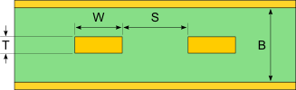
| Trace Thickness | T | ||
| Substrate Height | H1 | ||
| Trace Width | W | ||
| Trace Spacing | S | ||
| Substrate Dielectric | Er |
Differential Impedance The impedance measured between the two lines when they are driven with opposite polarity signals. Zdiff is equal to twice the value of Zodd
Odd Impedance The impedance measured when testing only one of the differential traces referenced to the ground plane. The differential signals need to be driven with opposite polarity signals. Zodd is equal to half of the value of Zdiff
Common Impedance The impedance measured between the two lines when they are driven with the same signal. Zcommon is half the value of Zeven
Even Impedance The impedance measured when testing only one of the differential traces referenced to the ground plane. The differential signals need to be driven with the same identical signal. Zeven is twice the value of Zcommon
Models have been created to approximate the characteristics of the microstrip transmission line.


 for (s/t) >= 5
 for (s/t) < 5


Edge coupled microstrip impedances (Z0,odd, Z0,even, Z0,diff and Z0,common) shall be calculated as specified in previous paragraph.
[1] IPC-2141A “Design Guide for High-Speed Controlled Impedance Circuit Boards”


