Czy wolisz polską wersję strony elektroda?
Nie, dziękuję Przekieruj mnie tam
| Trace Thickness | T | ||
| Trace Height Above Plane | H1 | ||
| Trace Height Above Plane | H2 | ||
| Trace Width | W | ||
| Substrate Dielectric | Er |
Models have been created to approximate the characteristics of the embedded microstrip transmission line. A good approximation is provided by the formulas contained in the document IPC-2141A. For an embedded (internal) microstrip, the formulas provided in paragraph 4.2.3 shall be used. The characteristic impedance is given by:
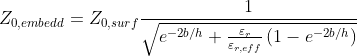 Eq. 1
Eq. 1
where Z0,surf can be computed as specified in Eq. 1 of the Microstrip Calculator using H2 in place of h, εr,eff can be computed as specified in Eq. 2 of the Microstrip Calculator, h=H1 and b=H2-H1.


