
I invite you to a short test and demonstration of the use of popular TM1637-based 7-segment display modules. I will run such a module first with Arduino and then without using any library, at the end I will also show an alternative, eliminating unnecessary delays library designed to control these modules.
Purchasing the chip Maybe this time we will start the topic with the issue of finances. How much does this module cost?
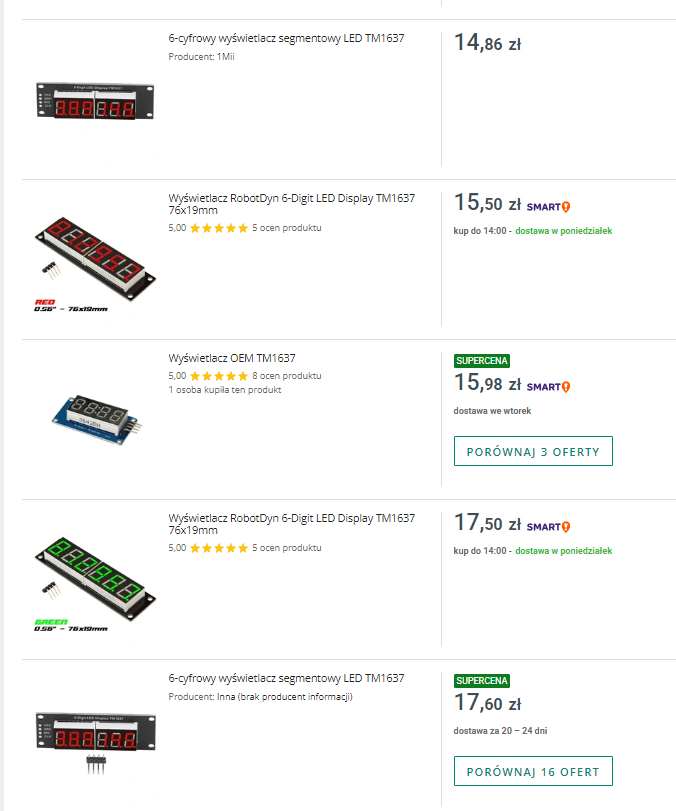
This time I have done the search on a Polish auction site.
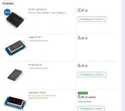
It is possible to buy both the same die, even for 2.5zł, as well as ready-made modules.
A 4-digit module costs about 6zl, and 6-digit modules are for more than 15zl:
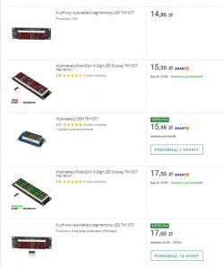
Postage will also cost about 10zl, unless you have purchased free postage, which I myself use on this portal. Unfortunately they are only valid from about 40/45zl of the order amount, so you still have to put something in the basket.
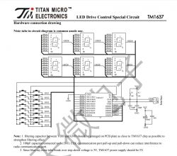
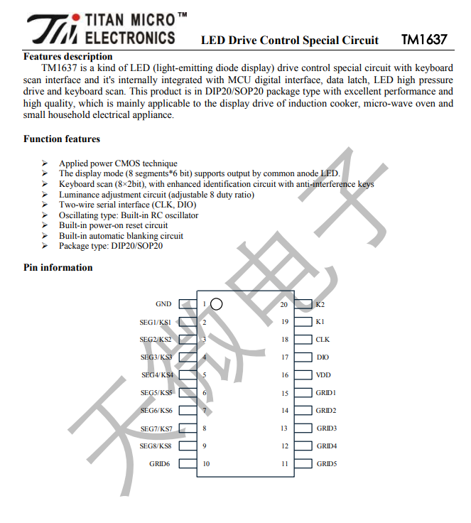
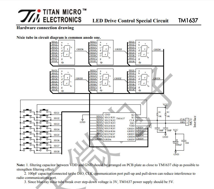
A bit of theory... A rather brief reading of the datasheet note. To start with, we are greeted by the chip's pinouts, but we have a ready-made module, so we don't need that:
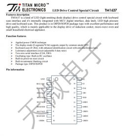
The chip can also handle a keyboard, but our modules don't support that.
Inputs:

6 grids, 8 segments.
This means 6 7-segment digits with e.g. an extra dot or a colon.
These CLK, ACK, sound a bit like I2C, but...
Unfortunately I2C is not. It doesn't even have chip addressing supported, i.e. you can't (as you could with I2C) connect several devices on one bus. Poorly.
Example application:
Buttons are connected to special ports K2 and K1, i.e. they do not receive our displays. It will be worth considering using this in the future, although I won't describe it here. There are quite a few of these buttons too, so you could make a nice keypad on this.
The parameters of the displays used (current per segment, etc.) are in the datasheet note.
Example in Arduino Most popular modules already have publicly available, free libraries for Arduino. This is also the case here. Everything on Github:
https://github.com/avishorp/TM1637 The library can also be found in the Arduino library builder and included automatically.
This is the full example code from this library:
But the whole thing can be simplified a bit.
The TM1637Display constructor takes two arguments - the index of the CLK and DIO pins.. The setBrightness function sets the brightness level (from 0 to 15) and turns on the segments (true to turn them on, false to turn them off).
The decimal value is shown by showNumberDec.
In addition, we have access directly to the segments (function setSegments) and the possibility to display a number with a dot (function showNumberDecEx). The setSegments function offers arguments to access the selected character (e.g. update only the two characters at positions 4 and 5), the first argument is the index of the first character and the second is the number of characters.
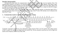
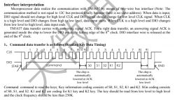
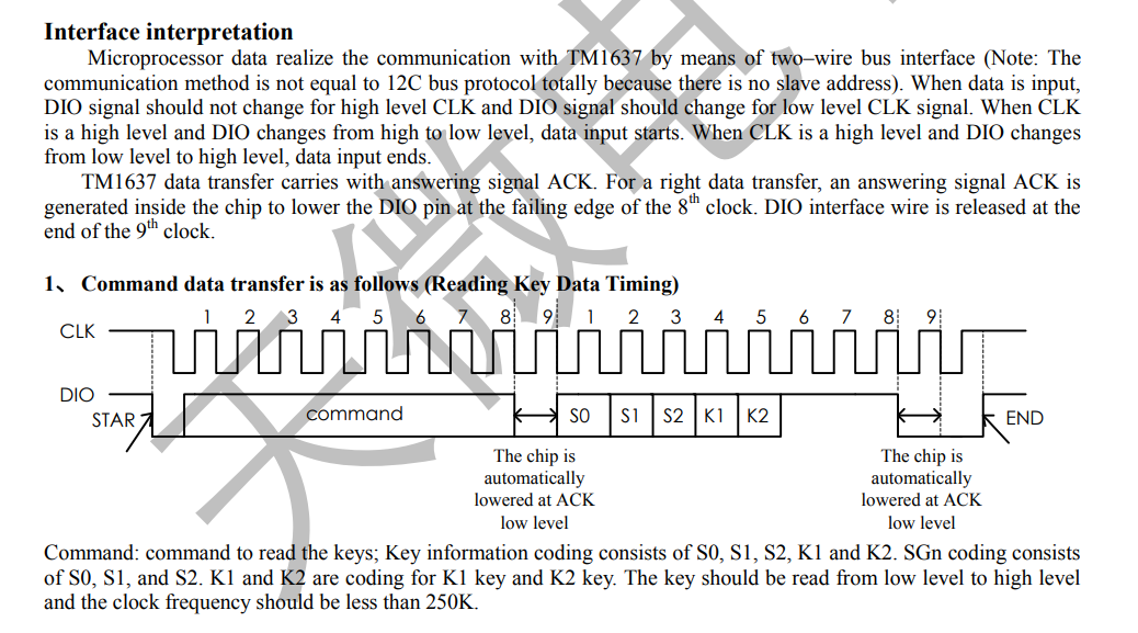
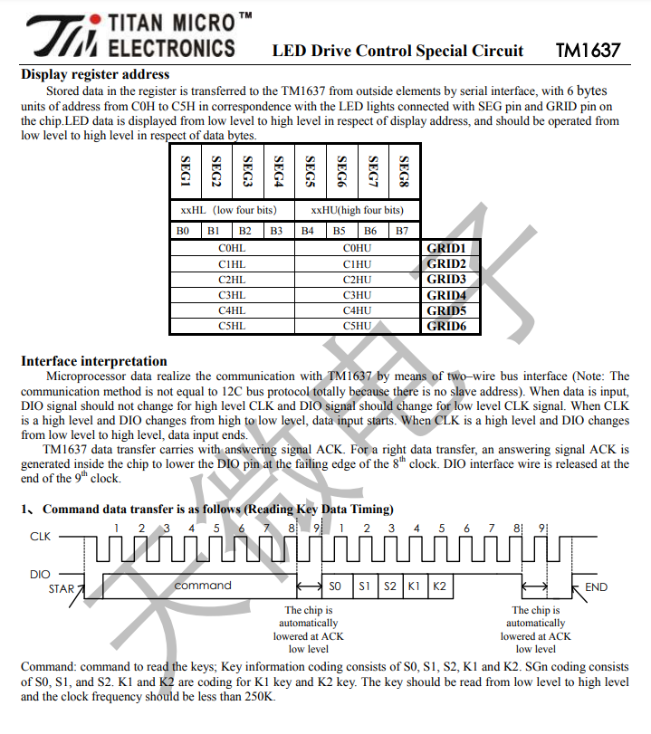
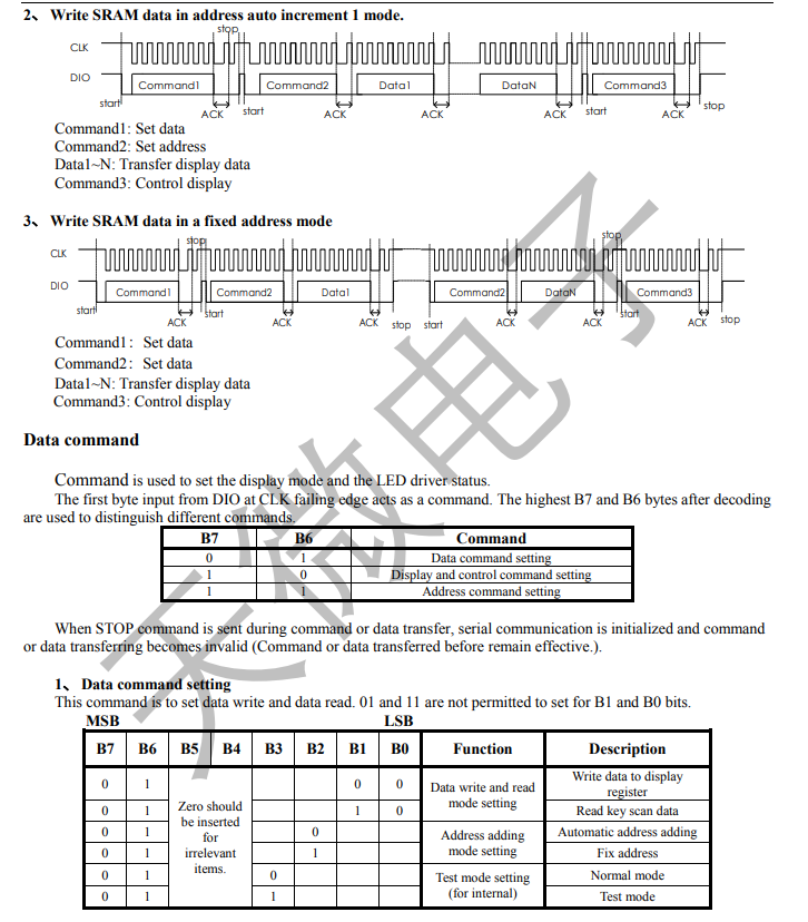
Example "on foot" The display protocol is known and described in the catalogue note:
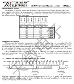
According to the protocol, in order to send
write data to display register first we need to transmit:
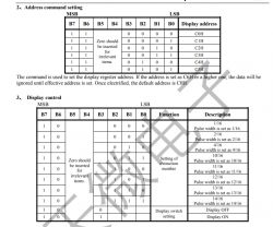
Then, after stop and restart we transmit the command to set the register we are writing to, i.e.:
With the 4 youngest bits set to the address of the first character we are updating. Usually this will be 0.
Then we transmit the next bytes (segment data).
Finally, we want to transmit
display control with state On/Off (bit 3) and brightness level (bits 2, 1 and 0):
Writing this in the code we get:
Following, the data formation of the third command I have already described (the on/off bit and the 3 bits of the brightness level), it is formed like this:
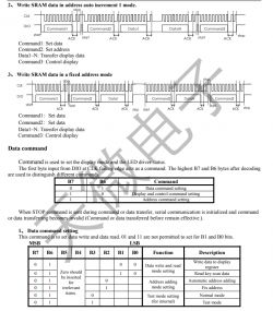
There are still our 3 auxiliary functions, namely the start condition, the stop condition and the byte send.
We start with the high states, then the DIO goes low, as well as the clock.
Then, for each bit, we set its value to DIO, and it is read by the chip at the rising edge of CLK (that is, as CLK goes from false to true, low to high).
Then, continuing with the byte send function, we have:
The clock performs another cycle. The DIO pin enters input mode. This is the moment that is marked on the diagram as
The chip is automatically lowered at ACK low level (between the falling edge of the 8th clock cycle and the end of the 9th clock cycle). We wait a moment and read the value from DIO. This is the ACK response. Based on it, you can check whether the circuit is responding. Then the DIO returns to output mode.
Finally, we return to the high states.
That's it. Of course, not I have defined here the actual segment maps that are required to correctly display the figures, but this can already be done on your own.
Communication speed The problem of no real I2C I have already discussed, but unfortunately this is not the only unpleasant surprise here. After looking into the source
TM1637Display.cpp we see that the communication code is strewn with delays (or more precisely there: bitDelay), defaulting to 100us. This is enough to make it worth doing something about. I myself in my code (quoted above) experimented a bit with reducing these delays, but there is a ready-made solution for this on the web too:
https://github.com/cphouser/TM1637-no-delay Library
TM1637-no-delay is implemented without the use of functions such as
delayMicroseconds . Has an interface to refresh the display without blocking the event loop. Requires an additional call to the function
update every 100us.
Below is an example of using this library (copied from their Github):
For exact timing requirements, please refer to the catalogue note.
Small problem with setSegments order Finally, I'd like to give a small comment/warning about setting segments. I don't know if this is a common problem, but in my case the display digits were connected in such a way that sending the character codes to it in this order:
Resulted in a display:
To fix this, you either have to physically rewire the GRID connections (as in the diagram posted above in this topic), or programmatically remap the segments via an array:
Indexes in C/CPP etc start from 0.
Effects gallery I don't really know what to show here. Probably best to start with a brightness level check:

Classic, countdown:
Digit test:
 Summary
 Before closer inspection, the module seemed to be more appealing.. After learning more about its performance, I found it to be slightly worse than I thought. I shouldn't complain, because I bought it anyway
at the request of a friend from Ukraine to be able to run it on BK7231N for him, but I really don't understand why the manufacturer didn't use normal I2C in this display. Being able to use one communication line (well, okay, two lines - SDA and SCL) for multiple devices is really very useful, and what would one more byte reception change for the manufacturer? And why is this communication so slow? It's a good thing that there are ready-made libraries for it on the web under Arduino, both in the blocking version and the one without latency.
Has anyone used this display in projects? Or does anyone know of an equally cheap module, but with an I2C interface? .


Comments
I have a question - does it shine too brightly on the lowest brightness in perfect darkness? I often feel that manufacturers underestimate the logarithmic nature of the human eye. When I made a frame displaying... [Read more]
I'd be happy to check this at night. At the moment I only know that the lowest brightness level, according to the datasheet, is 1/16 pulse width, and the full one looks like 14/16. As for the longevity... [Read more]
So quickly on such a 4-digit module +modul for strain gauge beams +arduino mini I made a tester for a quick check of strain gauge beams. Used a few times, it has been sitting in a drawer for 3-4 years.... [Read more]
Of course, I also use such a display. On my desk I have a thermometer built on TM1637+STM32F030F4P6+BMP280. [Read more]
I understand that it lights up non-stop. How long has it been running? [Read more]
Recently, I've been playing with modules based on the MAX7219 - driver for 8 7-segment displays (either its own digit patterns or independent segment control) or one 8*8 matrix - all in all, it amounts... [Read more]
I once ran the MAX7219 in 8x8 form on a PIC18F45K50 and posted the control code on the forum: https://www.elektroda.pl/rtvforum/topic3594728.html [Read more]
The thermometer has been running non-stop since July [Read more]
I inserted such a circuit in the soldering iron. There were no cheap displays on the MAX7219 ready yet. I was still writing in bascom and had to do a lot of fiddling to figure it out. Displays on the... [Read more]
And it would be enough if the manufacturers used a logarithmic scale. With 16 levels, it would be enough for each level to be 2/3 the size of the previous one. Then the lowest brightness would be 0.002... [Read more]
Find out how this type of function is implemented at the hardware level, because in isolation from the hardware one can dream up various visions, nevertheless, the logic of the design dictates certain... [Read more]
You are right - I guess I look at such specialised circuits too much through the prism of MCU capabilities. [Read more]
As for lifespan, I made myself a co2 'meter' and a chad warning device, it has been going 24/7 for many months. I have the 2x4 display version + 8 micro buttons. [Read more]