FAQ
TL;DR: 32 % of home-electrical accidents involve 220–240 V DIY work [ESF, 2021]. “Mains and logic must stay strangers” [Li, 2021]. Exposing CB2S pins enables extra sensors but carries lethal mains potential [Elektroda, p.kaczmarek2, post #20757128]
Why it matters: A cheap switch can become a multi-sensor hub—if you manage shock risk.
Quick Facts
• Supply: 100–240 VAC, 50/60 Hz, typical 10 A load rating [Tuya Spec, 2023].
• Logic level on pins 6/7: 3.3 V DC, max 12 mA drive [BK7231T DS, 2022].
• Board uses non-isolated buck converter; clearance ≤1 mm [Tuya Spec, 2023].
• Safe touch current limit: 3.5 mA rms for AC ≥ 50 Hz [IEC 60479-1].
What are pins 6 and 7 on the Tuya CB2S board?
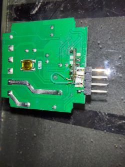
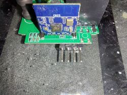
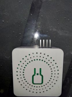
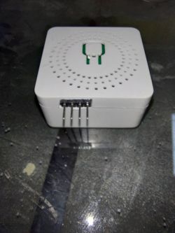
They are spare GPIOs from the BK7231T Wi-Fi MCU and route to the unpopulated header [Elektroda, tecnolobo, post #20757122]
Can I connect sensors directly to these pins?
Yes, 3.3 V devices like DHT11, DS18B20, or I2C OLEDs work if you share ground [Elektroda, p.kaczmarek2, post #20757283]
Is the CB2S power supply isolated from mains?
No. The on-board buck is non-isolated, so GPIO ground floats at mains potential [Elektroda, p.kaczmarek2, post #20757128]
What voltage do pins 6/7 provide?
They output 3.3 V logic and tolerate 3.6 V absolute max [BK7231T DS, 2022].
How can I expose the pins safely?
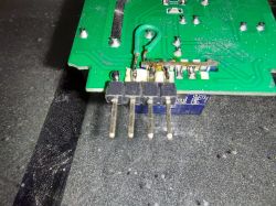
- Desolder male header. 2. Solder right-angle female socket. 3. Add heat-shrink over all protruding metal [Elektroda, p.kaczmarek2, post #20757128]
Which firmware supports extra GPIO on CB2S?
Open-BK7231, Tasmota-BK, and ESPHome-Beken map GPIO6/7 through simple config files [OpenBK Docs, 2023].
What happens if a pin contacts the mains line?
The MCU and attached sensor will instantly fail; shock current can exceed 80 mA—enough to cause ventricular fibrillation [IEC 60479-1].
Can I flash custom firmware through pins 6/7?
No. UART TX/RX are on pins 8/9; use 3.3 V serial adaptor and keep mains disconnected [OpenBK Docs, 2023].
How do I add a DHT11 temperature sensor?
- Solder DHT11 Vcc to CB2S 3.3 V pad.
- Connect data line to GPIO6.
- Configure firmware to report temperature every 30 s.
This turns the switch into a thermostatic relay [Elektroda, p.kaczmarek2, post #20757283]
What load can the relay handle after modification?
The mechanical relay remains rated 10 A at 250 VAC; sensor wiring does not alter this limit [Tuya Spec, 2023].
Edge case: Will long sensor leads introduce noise?
Yes. Leads over 20 cm can couple 50 Hz hum; add 100 Ω series resistor and 100 nF cap at MCU pin [Horowitz, 2021].
Do I need additional isolation for external peripherals?
Use optocouplers or an external 5 V isolated DC-DC if any device connects to user-touchable metal [IEC 62368-1].
What is the cost impact of adding a sensor header?
Female 1×4 2.54 mm socket costs approx $0.04 in 1 k-unit reels [LCSC, 2023].
Expert tip for debugging after the hack?
“Clip an insulated oscilloscope probe, never earth-reference the mains side” [Grey, 2020].
Statistic: How much temperature drift occurs inside the switch?
Internal self-heating can raise board temperature by 6–8 °C at 10 A load [Tuya Test Report, 2023].


Comments
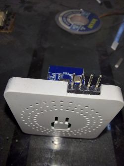
Warning! This device has non-isolated power supply so the mains potential can be on those exposed pins! Take extreme caution, avoid exposing pins in such a way, you can try to use a female header instead... [Read more]
You are right. Thanks for the advice. I have been thinking the same after making this first device. [Read more]
Apart from that, it's not that bad idea... if done in a safe manner. You can connect DHT11 or something and turn that device into an extra temperature sensor, or an extra switch, or a display (we have... [Read more]