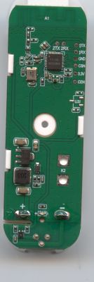
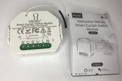
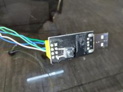
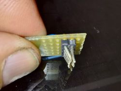
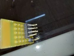
Here are the photos of the disassembly of the "Tuya Mini Smart Switch" sold in Brazil.
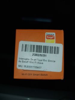
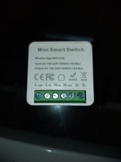
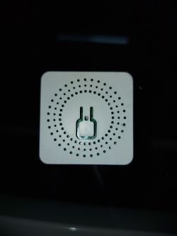
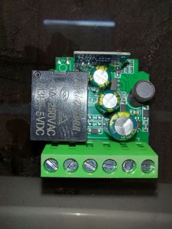
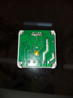
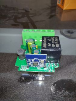
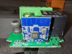
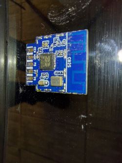
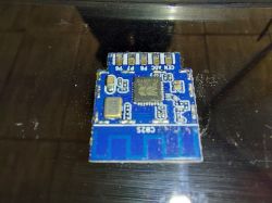
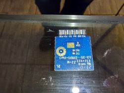
It also follows the original firmware downloaded and the pinout used on that device.
Pins Order from Left to Right
CB2S - Front
Pin 1 - 3V3
Pin 2 - Ground
Pin 3 - RX1 - Input Button (I/O, UART_RX1, corresponds to P10 of the IC)
Pin 4 - TX1 - None (I/O, UART_TX1, corresponds to P11 of the IC)
Pin 5 - P24 - None (Support hardware PWM and correspond to P24 of the IC)
Pin 6 - P26 - Output Relay (Support hardware PWM and correspond to P26 of the IC)
CB2S - Back
Pin 7 - CEN - None
Pin 8 - ADC - Input S1-S2 (I/O, ADC, which corresponds to P23 of the IC)
Pin 9 - P8 - Output LED (I/O, Support hardware PWM and correspond to P8 of the IC)
Pin 10 - P7 - None
Pin 11 - P6 - None


