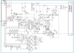
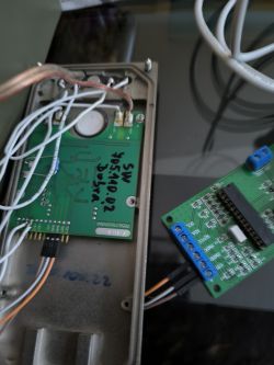
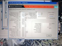
Description of the "reset" of electronics in laptop batteries based on BQ2040, BQ2060, BQ2063 chips and EEPROM 24C01, 24C02, 24C04 memories using the SBWorkshop 3.71 program
You can also use the Be2Works program up to version 2.85 inclusive.
Attention: On March 12, 2012, a new version of Be2Works (v3.0) was released. Unfortunately, the LPT port was abandoned in favor of USB. One of the two interfaces is required to work with the program: USB to GPIO IT companies or EV2300.
In the appendix, the Be2Works program version 2.82.2, which works with the I2C interface described below.
Many laptop users suffer from bad batteries. The most common reasons for this are worn-out cells or improper recording in the internal EEPROM about the state of cells in the battery. The most common reason for this is improper operation. This does not mean, however, that the battery is only suitable for disposal. Assuming that the electronics and cells inside the battery are in working order, we can bring the battery back to life. In the case of worn or damaged cells, it will be necessary to replace them with new ones, which is a cheaper solution than buying a whole new battery. You should not only replace individual cells, but the complete set, due to the difference in capacity between already partially used cells and new cells. The mere exchange of cells, most often gives nothing and the battery still refuses to cooperate, which is caused by incorrect information stored in the EEPROM memory that needs to be changed, i.e. "Reset"
While searching the Internet for information on how to restore the battery to life, I came across many descriptions of how to do it, but all of them were based only on editing the contents of individual EEPROM memory cells. What, if incorrectly changed, can lead to damage to the cells, and in the worst case to an explosion or ignition.
The most appropriate solution turned out to be the use of the SBWorkshop program, which makes appropriate changes to the memory content for us, and also allows you to read all battery parameters. The demo version of this program has no restrictions for BQ20xx / 24Cxx chips, which in our example is completely sufficient.
The example description concerns a battery from a Fujitsu-Siemens Amilo D 7830, 755-4S4000-S1P1 laptop with a voltage of 14.4V and a capacity of 4000mAh, based on the BQ2060A chip and EEPROM 24C02 memory. Symptoms: The laptop works on the battery for about 5 minutes. Charging takes a very short time, about 30 minutes.
What will we need?
[letter: ae9cbf4331] 1. SBWorkshop 3.1 Demo
2. Interface for EEPROM programming and battery data reading
3. Soldering iron
4. Multimeter
5. Bulb 12V / 21W [/ letter: u: ae9cbf4331]
Elements for building the I?C interface:
[letter: ae9cbf4331] 1. System 74LS05 or 74LS06 - 1 pc.
2. 10 k? resistors - 6 pcs.
3. Capacitor 100nF - 1 pc.
4. DB25 male plug with housing - 1 pc.
5. USB or PS2 mouse cable - 1 pc.
6. Connectors with four contacts - 4 pcs.
7. Socket for the DIL14 chip - 1 pc.
8. One-sided laminate with dimensions of 55x59 mm - 1 pc.
9.1m four-core cable. [/ Letter: u: ae9cbf4331]
Construction of the interface
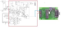
The first thing we need to do is build an interface for communicating with the battery and for programming the EEPROM memory. If you prefer, you can build it on a piece of a printed circuit board or on the so-called "Spider", that is, directly connect all elements in the air with short wires. Then close the whole thing in the DB25 plug housing, leading out only the USB or PS2 power cable and connecting the battery. Make sure that the DB25 connector housing is not metallized. In the case of metallized, it is necessary to line the inside with a piece of cardboard to avoid short circuits after inserting the assembled system into it.
Connect the wire from the old mouse to the J2 connector, of course, checking beforehand which wire of the wire is the plus of the power supply and ground, do not connect the other wires. Note: To power the interface, use the USB, PS2 or other + 5V power source, not the battery being diagnosed! J3 is for EEPROM programming and J4 is for reading battery data. In fact, the J3 and J4 connectors do not differ in any way, except for the lack of + 5V power supply in J4. This is a deliberate solution, because we do not need + 5V to read data from the battery, and using the same cable as for EEPROM programming, a free wire with + 5V may accidentally cause a short circuit. We only need to move the cable to the appropriate connector depending on what we want to do. The J5 connector is used for programming other systems, but in the demo version of the program, these systems are locked and a license is required. Although we are not going to use this connector, I put it on the PCB and the schematic in case someone decides to buy the full version of the program.
After assembling the interface and checking the correctness of assembly, we can connect it to the parallel port of the computer and the power supply, and then run the SBWorkshop program. We should get the message "Adapter OK." In the lower left corner of the window. Otherwise, it means that the interface is not working properly and you should look for where we made a mistake in the assembly.
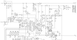
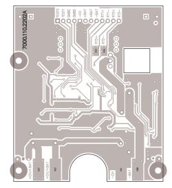
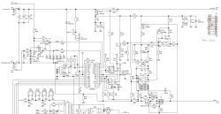
Below is a diagram and the layout of the interface board from the print side.
Attention: The printout of the paths is prepared for the exposure method. If we make a tile using the thermal method, then the image of the paths must be mirrored.
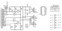
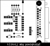
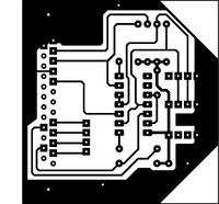
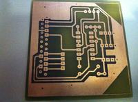
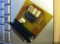 tile made by volvbast1
Reading the battery parameters
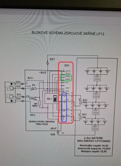
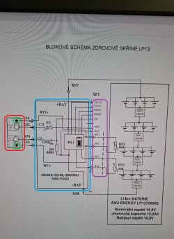
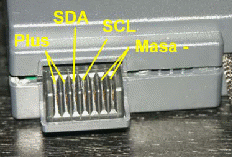
After successfully launching the interface, the next thing we will do is read our battery parameters. To do this, first determine which contacts of the battery connector are on the SM-Bus. When measuring the voltage between the contacts with a multimeter, we need to find the contacts with the voltage corresponding to the battery voltage, i.e. in the range of 12 to 14 V depending on the state of charge of the battery and determine where the plus and minus are. There are 1.2 plus and 6.7 minus contact pairs in our battery. On two of the three others, i.e. 3,4 and 5, there must be an SM-Bus bus in this case. We connect the GND wire from the wire from the interface connector J4 to the battery minus, and the wires with SDA and SCL signals, successively to contacts 3, 4 and 5 using different connection combinations, and after each change of the combination we try to read the data in the "Battery data" tab by clicking on the "Read Bartery" button. If the combination is correct, the program will read the battery data, otherwise the parameter fields will remain blank and we will receive the message "Battery not found". In order to be able to compare the changes we made during the "Reset" later, we save the report by clicking on "Save Report". In the case of completely discharged cells, reading is impossible!
EEPROM reading and reset
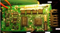
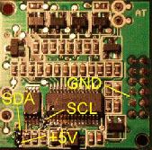
We carefully disassemble the battery. As we have already done this, inside we find a PCB with the battery electronics. In our case, it will be two plates one above the other in the middle of the battery, connected with each other by a connector. On one of them it will find the EEPROM 24C02 memory we are interested in. Now we unsolder the four wires from the cells, connecting the electronics with the cells. We start with the plus of the first link and end with the minus of the last link. Leave the wires going to the battery connector. We take the plates out of the battery and look for EEPROM 24C02 memory on them. After locating the deck, check if there are any contact pads on the board next to the memory and if any of them connect to the memory pins 5, 6, 7 and 8.
If there is such, the task is easier and we do not have to desolder the circuit from the board. Now, with a multimeter in the ohmmeter range, we check whether the memory foot 7 is permanently connected to the ground.
If not, we have to connect it to the ground of the system. Then, from the memory catalog note, we read the pins on which the SDA, SCL and power signals are located. I will suggest that for the 24Cxx memory series in a housing with eight pins, these are pins 5 - SDA, 6 - SCL and 8 - + 5V.
When we know where they are, what are the signals, all we have to do is read the EEPROM and save its contents on the disk for safetyCarefully solder the wires of the four-wire interface cable to the contact pads on the board, paying attention that the wires with the SDA, SCL and + 5V signals from the J3 interface connector are connected to their memory counterparts. We connect the wire with GND to the mass of the plate. After checking the correctness of the connections, connect the interface to the parallel port (printer) of the computer and the power cord to the USB or PS2 port or other + 5V power source.
In the SBWorkshop program, go to the "Eeprom Read / Write / Reset" tab. There are three fields there. In the first one, we set the "Chipset" of our battery, that is, the supervisory system and EEPROM. We choose BQ2060 / BQ2063 / 24C01 / 24C02 because our battery has BQ2060 and 24C02.
The second field is used for reading and writing the EEPROM memory. Here we select our memory type, which is 24C02 and click on "Save Eeprom" to save a backup copy of the EEPROM content on our computer's hard drive. When you restore the old content or enter a different one, indicate the previously saved file in the field below and click on "Write Eeprom".
In the third field, we have a preview of the basic data contained in the file that we intend to save to the EEPROM in the second field.
If we saved a backup copy of our memory, we can now perform a "Reset". We go back to the first field and click on "Reset Eeprom". After that, disconnect the interface from the power supply and the computer and unsolder the wires from the board. Then solder the wires to the cells again, starting with the mass of the last cell and ending with the plus of the first one. If someone is curious what changes were made during the reset, he can save the eeprom memory contents in the second field and compare their contents in some Hexeditor.
Cell condition test
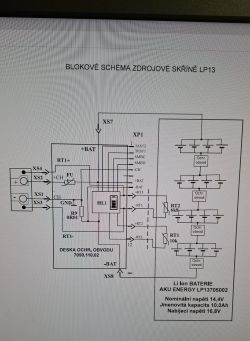
Now is the time to take a closer look at the states of our battery cells. The cells in our battery are connected in pairs in series, i.e. two cells in parallel constitute a pair and four such pairs are connected in series. For this purpose, we will need a 12V / 21W bulb. We connect the bulb to the ends of the row, that is, the plus of the first pair and the minus of the last pair. Then, with a multimeter, we measure the voltages on individual pairs. If a pair has a much lower voltage or drops sharply than the others, it may be a sign of damage to these cells or an unequal charge level of the cells. Single pairs should then be discharged with a bulb less to the same voltage level under load as the weakest pair of cells. However, it should be remembered that the voltage on a pair of cells should not drop below 3V. If the weakest pair has a voltage lower than 3 V, then it should be charged to the voltage of the other sections using a power supply with voltage limitation 4.2 V and current 1 A.
Battery startup
Put the discharged cells into the housing, insert the electronics board and re-solder the connections between the board and the cells. We put the housing together, but do not glue it together yet, because it may be necessary to replace the cells. Now we put the battery into the laptop for a moment and connect the power adapter so that the battery charging indicator lights up. This is necessary for the battery driver to take effect.
Then we take the battery out of the laptop and read its parameters again, as it was described earlier. If the battery charge cycle status (CycleCount) has been reset, the FCC charge capacity has been equal to the factory DC, that is, the "reset" has been performed correctly. We put the battery into the laptop and charge it until the charging process is completed and then we turn on the laptop.
Then run the BatteryMon program, disconnect the power supply and check how long it will work and whether the discharge characteristic is smooth. If the working time has not been extended and the graph drops sharply, this means that cells are worn out and need to be replaced with new ones. If someone has good used cells with the same voltage and capacity, he can replace the damaged pair, but this does not guarantee that the battery will function properly.
If the laptop does not see the battery at all or does not charge it, check the fuses. If the fuses are ok, re-enter the old eeprom content and try "reset" again. If it did not work, it may indicate that the electronics in the battery are damaged and we have to buy a new battery or get the same electronic board in good working order.
If everything went well, we can glue the battery again and be happy to save it.
The author of the above FAQ is Damian Nawrath [Kabelek@gmx.de]. He corrected and completed jarob.
You can also use the Be2Works program up to version 2.85 inclusive.
Attention: On March 12, 2012, a new version of Be2Works (v3.0) was released. Unfortunately, the LPT port was abandoned in favor of USB. One of the two interfaces is required to work with the program: USB to GPIO IT companies or EV2300.
In the appendix, the Be2Works program version 2.82.2, which works with the I2C interface described below.
Many laptop users suffer from bad batteries. The most common reasons for this are worn-out cells or improper recording in the internal EEPROM about the state of cells in the battery. The most common reason for this is improper operation. This does not mean, however, that the battery is only suitable for disposal. Assuming that the electronics and cells inside the battery are in working order, we can bring the battery back to life. In the case of worn or damaged cells, it will be necessary to replace them with new ones, which is a cheaper solution than buying a whole new battery. You should not only replace individual cells, but the complete set, due to the difference in capacity between already partially used cells and new cells. The mere exchange of cells, most often gives nothing and the battery still refuses to cooperate, which is caused by incorrect information stored in the EEPROM memory that needs to be changed, i.e. "Reset"
While searching the Internet for information on how to restore the battery to life, I came across many descriptions of how to do it, but all of them were based only on editing the contents of individual EEPROM memory cells. What, if incorrectly changed, can lead to damage to the cells, and in the worst case to an explosion or ignition.
The most appropriate solution turned out to be the use of the SBWorkshop program, which makes appropriate changes to the memory content for us, and also allows you to read all battery parameters. The demo version of this program has no restrictions for BQ20xx / 24Cxx chips, which in our example is completely sufficient.
The example description concerns a battery from a Fujitsu-Siemens Amilo D 7830, 755-4S4000-S1P1 laptop with a voltage of 14.4V and a capacity of 4000mAh, based on the BQ2060A chip and EEPROM 24C02 memory. Symptoms: The laptop works on the battery for about 5 minutes. Charging takes a very short time, about 30 minutes.
What will we need?
[letter: ae9cbf4331] 1. SBWorkshop 3.1 Demo
2. Interface for EEPROM programming and battery data reading
3. Soldering iron
4. Multimeter
5. Bulb 12V / 21W [/ letter: u: ae9cbf4331]
Elements for building the I?C interface:
[letter: ae9cbf4331] 1. System 74LS05 or 74LS06 - 1 pc.
2. 10 k? resistors - 6 pcs.
3. Capacitor 100nF - 1 pc.
4. DB25 male plug with housing - 1 pc.
5. USB or PS2 mouse cable - 1 pc.
6. Connectors with four contacts - 4 pcs.
7. Socket for the DIL14 chip - 1 pc.
8. One-sided laminate with dimensions of 55x59 mm - 1 pc.
9.1m four-core cable. [/ Letter: u: ae9cbf4331]
Construction of the interface
The first thing we need to do is build an interface for communicating with the battery and for programming the EEPROM memory. If you prefer, you can build it on a piece of a printed circuit board or on the so-called "Spider", that is, directly connect all elements in the air with short wires. Then close the whole thing in the DB25 plug housing, leading out only the USB or PS2 power cable and connecting the battery. Make sure that the DB25 connector housing is not metallized. In the case of metallized, it is necessary to line the inside with a piece of cardboard to avoid short circuits after inserting the assembled system into it.
Connect the wire from the old mouse to the J2 connector, of course, checking beforehand which wire of the wire is the plus of the power supply and ground, do not connect the other wires. Note: To power the interface, use the USB, PS2 or other + 5V power source, not the battery being diagnosed! J3 is for EEPROM programming and J4 is for reading battery data. In fact, the J3 and J4 connectors do not differ in any way, except for the lack of + 5V power supply in J4. This is a deliberate solution, because we do not need + 5V to read data from the battery, and using the same cable as for EEPROM programming, a free wire with + 5V may accidentally cause a short circuit. We only need to move the cable to the appropriate connector depending on what we want to do. The J5 connector is used for programming other systems, but in the demo version of the program, these systems are locked and a license is required. Although we are not going to use this connector, I put it on the PCB and the schematic in case someone decides to buy the full version of the program.
After assembling the interface and checking the correctness of assembly, we can connect it to the parallel port of the computer and the power supply, and then run the SBWorkshop program. We should get the message "Adapter OK." In the lower left corner of the window. Otherwise, it means that the interface is not working properly and you should look for where we made a mistake in the assembly.
Below is a diagram and the layout of the interface board from the print side.
Attention: The printout of the paths is prepared for the exposure method. If we make a tile using the thermal method, then the image of the paths must be mirrored.


 tile made by volvbast1
 Reading the battery parameters
After successfully launching the interface, the next thing we will do is read our battery parameters. To do this, first determine which contacts of the battery connector are on the SM-Bus. When measuring the voltage between the contacts with a multimeter, we need to find the contacts with the voltage corresponding to the battery voltage, i.e. in the range of 12 to 14 V depending on the state of charge of the battery and determine where the plus and minus are. There are 1.2 plus and 6.7 minus contact pairs in our battery. On two of the three others, i.e. 3,4 and 5, there must be an SM-Bus bus in this case. We connect the GND wire from the wire from the interface connector J4 to the battery minus, and the wires with SDA and SCL signals, successively to contacts 3, 4 and 5 using different connection combinations, and after each change of the combination we try to read the data in the "Battery data" tab by clicking on the "Read Bartery" button. If the combination is correct, the program will read the battery data, otherwise the parameter fields will remain blank and we will receive the message "Battery not found". In order to be able to compare the changes we made during the "Reset" later, we save the report by clicking on "Save Report". In the case of completely discharged cells, reading is impossible!

EEPROM reading and reset
We carefully disassemble the battery. As we have already done this, inside we find a PCB with the battery electronics. In our case, it will be two plates one above the other in the middle of the battery, connected with each other by a connector. On one of them it will find the EEPROM 24C02 memory we are interested in. Now we unsolder the four wires from the cells, connecting the electronics with the cells. We start with the plus of the first link and end with the minus of the last link. Leave the wires going to the battery connector. We take the plates out of the battery and look for EEPROM 24C02 memory on them. After locating the deck, check if there are any contact pads on the board next to the memory and if any of them connect to the memory pins 5, 6, 7 and 8.
If there is such, the task is easier and we do not have to desolder the circuit from the board. Now, with a multimeter in the ohmmeter range, we check whether the memory foot 7 is permanently connected to the ground.
If not, we have to connect it to the ground of the system. Then, from the memory catalog note, we read the pins on which the SDA, SCL and power signals are located. I will suggest that for the 24Cxx memory series in a housing with eight pins, these are pins 5 - SDA, 6 - SCL and 8 - + 5V.
When we know where they are, what are the signals, all we have to do is read the EEPROM and save its contents on the disk for safetyCarefully solder the wires of the four-wire interface cable to the contact pads on the board, paying attention that the wires with the SDA, SCL and + 5V signals from the J3 interface connector are connected to their memory counterparts. We connect the wire with GND to the mass of the plate. After checking the correctness of the connections, connect the interface to the parallel port (printer) of the computer and the power cord to the USB or PS2 port or other + 5V power source.

In the SBWorkshop program, go to the "Eeprom Read / Write / Reset" tab. There are three fields there. In the first one, we set the "Chipset" of our battery, that is, the supervisory system and EEPROM. We choose BQ2060 / BQ2063 / 24C01 / 24C02 because our battery has BQ2060 and 24C02.
The second field is used for reading and writing the EEPROM memory. Here we select our memory type, which is 24C02 and click on "Save Eeprom" to save a backup copy of the EEPROM content on our computer's hard drive. When you restore the old content or enter a different one, indicate the previously saved file in the field below and click on "Write Eeprom".
In the third field, we have a preview of the basic data contained in the file that we intend to save to the EEPROM in the second field.
If we saved a backup copy of our memory, we can now perform a "Reset". We go back to the first field and click on "Reset Eeprom". After that, disconnect the interface from the power supply and the computer and unsolder the wires from the board. Then solder the wires to the cells again, starting with the mass of the last cell and ending with the plus of the first one. If someone is curious what changes were made during the reset, he can save the eeprom memory contents in the second field and compare their contents in some Hexeditor.
Cell condition test
Now is the time to take a closer look at the states of our battery cells. The cells in our battery are connected in pairs in series, i.e. two cells in parallel constitute a pair and four such pairs are connected in series. For this purpose, we will need a 12V / 21W bulb. We connect the bulb to the ends of the row, that is, the plus of the first pair and the minus of the last pair. Then, with a multimeter, we measure the voltages on individual pairs. If a pair has a much lower voltage or drops sharply than the others, it may be a sign of damage to these cells or an unequal charge level of the cells. Single pairs should then be discharged with a bulb less to the same voltage level under load as the weakest pair of cells. However, it should be remembered that the voltage on a pair of cells should not drop below 3V. If the weakest pair has a voltage lower than 3 V, then it should be charged to the voltage of the other sections using a power supply with voltage limitation 4.2 V and current 1 A.
Battery startup
Put the discharged cells into the housing, insert the electronics board and re-solder the connections between the board and the cells. We put the housing together, but do not glue it together yet, because it may be necessary to replace the cells. Now we put the battery into the laptop for a moment and connect the power adapter so that the battery charging indicator lights up. This is necessary for the battery driver to take effect.
Then we take the battery out of the laptop and read its parameters again, as it was described earlier. If the battery charge cycle status (CycleCount) has been reset, the FCC charge capacity has been equal to the factory DC, that is, the "reset" has been performed correctly. We put the battery into the laptop and charge it until the charging process is completed and then we turn on the laptop.
Then run the BatteryMon program, disconnect the power supply and check how long it will work and whether the discharge characteristic is smooth. If the working time has not been extended and the graph drops sharply, this means that cells are worn out and need to be replaced with new ones. If someone has good used cells with the same voltage and capacity, he can replace the damaged pair, but this does not guarantee that the battery will function properly.
If the laptop does not see the battery at all or does not charge it, check the fuses. If the fuses are ok, re-enter the old eeprom content and try "reset" again. If it did not work, it may indicate that the electronics in the battery are damaged and we have to buy a new battery or get the same electronic board in good working order.
If everything went well, we can glue the battery again and be happy to save it.
The author of the above FAQ is Damian Nawrath [Kabelek@gmx.de]. He corrected and completed jarob.


