siwy24 wrote: (-) I turned off the injection supply from the rail and it turns out that the pump does not supply oil to the common rail. Proven pressure regulator. Bundles for kittens and electricity ok. I will add the continental pump number PSA 9672605380.
Find out exactly which injection system resides in your engine, do it first. It is very important due to the fact that when taking fuel from the tank (what is a "feeder in the tank"?)
hypertension or
underpressure . The overpressure comes from an electric pump immersed in the tank. This solution is used only by BOSCH and therefore if you have this system at home, the cause of the fault is almost certainly the electric pump, not the high pressure pump (pwc), secondly.
On the other hand
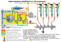
underpressure they produce the other systems, and therefore also CONTINENTAL, i.e. the SIEMENS you mentioned. Therefore, I throw in the SIEMENS fuel circuit diagram and advise you to study it carefully before replacing the possibly fully functional pwc.

You should start all over again. If the pressure in the reservoir (7) was measured using the pressure sensor (8) and it was as you write:
Quote: -Pressure 1 bar
means:
1) sensor failure (8),
2) damage to the flow and pressure regulators (3 and 4).
3) hydraulic, mechanical and electrical damage to the injectors (5).
At the beginning, damage to the injectors can probably be ruled out due to their faultless operation until the engine stops. After all, they could not get burned or damaged during the stop. Unless they had a problem before and the fault code applied to them:
Quote: P2291 - Injector Control Pressure, engine cranking, pressure too low. / Injector control, engine starting, fuel pressure too low.
The fuel pressure sensor is electrically checked not only on the sensor side but also
cables and
contacts . So it was the mechanics' first mistake to ignore the electrical wires the computer treats as a circuit as a whole. Up to 20 more sensors can be replaced and the fault will not disappear until the fault on the wiring side is corrected. Moreover, what does that mean
"the pump does not deliver oil to the rail" ? If you found this on the basis of a faulty sensor, and not by measuring the pressure directly, then your words, unfortunately, are not credible for obvious reasons - the sensor may be fully operational, and the cables and contacts to ...
A similar situation takes place in the pressure regulation you write about:
Quote: The pump gives nothing or nothing to the rail. The regulator was replaced from another car.
The pressure is regulated by a 2-valve, and for this
electrically and
hydraulically . Thus, there is a third factor to the electrics of the solenoid valve and the wiring, namely the hydraulics. If you took out the flow regulator (3) and the oil was flowing, it was a test of just one medium, i.e. the hydraulics. What about the electric supply when the regulator is mounted on the pwc? What about the zrwc (4) which also works hydraulically and electrically?
It should be remembered at this point that a very important issue is that the flow regulators (3) come in two versions:
closed and open without electricity . If we are dealing with the first case, i.e. the solenoid valve closed without current, it means that the pwc (1) is not receiving a gram of fuel from the nc pump (2), if there is e.g. a power cut to the solenoid coil of the valve. The pump (2) simply "grind" the fuel, which does not pass through the regulator (3), but returns back to the vacuum circuit (blue) via the pressure limiter (6). Pwc does not reach the normative pressure, despite its full efficiency. The entire injection system is in excellent condition, and the only fault is the lack of electric power or its disturbance to the regulator (3).
Another mistake could have been made by the mechanics at the second valve number 4. It may also be fully open and the fuel instead of to the reservoir (7) escapes through the overflow (yellow color) to the tank. Therefore, the pressure on the rail reaches only 1 bar during start-up, despite the faultless operation of the entire circuit, including the PVC and injectors.
The diagram clearly shows that there are as many as 4 pressures in the fuel circuit at the same time. They are all hydraulically and electrically controlled via two computer smoothly controlled solenoid valves, i.e. No. 3 and 4, and one non-electric valve (6). The final stage, i.e. the injectors (5), is also controlled twice, i.e. hydraulically and electrically. Neither has been tested, and it is uncertain whether any of them are good or bad.
You are right to refrain from rash disassembly and thus unnecessary interference with the timing, because the pwc defect has not been diagnosed with 100% certainty, only 30%, or even less.
I propose to focus on three things, namely:
1. Does metal filings reside in the fuel? or other contaminantsshown in the topic?
here . The presence of metal chips or "powder" at the bottom of the filter can would indicate the destructive effect of too "dry" fuel on the PVC.
2. Are there pressures within the specified limits in the fuel circuit? as in the diagram - blue, green, yellow and red? If these values do not fit the given "limits", but there are deviations in negative pressure (blue), low pressure (green) or overflow (yellow), then the final pressure (red) will be defective, extremely low here . No wonder the computer refuses to ignite because there is no fuel on the injectors.
3. Are the injectors leaking or otherwise damaged? here Kisses KotBury2


