logo elektroda
logo elektroda
X
logo elektroda

Multimeter - Understanding x.5 and x.75 Digits: Explaining Display Ranges in Newer & Older Models

dbs123 15789 19
ADVERTISEMENT
Treść została przetłumaczona polish » english Zobacz oryginalną wersję tematu
  • #1 15920830
    dbs123
    Level 9  
    Hello
    Can someone explain to me in pathological terms what x.5 x.75 digits mean in multimeters?
    I found info that in newer meters there is +20% to the range, but how is it in older ones?

    Will, for example, on meters 3 and 3.5 there will be 3 digits on the display or what?? If so, why the 5's?

    Please help.
    Regards!
  • ADVERTISEMENT
  • #2 15920843
    Karaczan
    Level 42  
    These half digits are, for example, "1", so instead of 999, it can be 1000.
    It's the "-" sign.
  • #3 15920860
    dbs123
    Level 9  
    How can it be 1000 when I only have 3 digits and not 4? unless it's 1000 states, as I read somewhere, i.e. 0 and the rest 999, but it's probably even without this .5 it can be like that.
  • ADVERTISEMENT
  • #4 15920868
    excray
    Level 41  
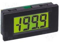
    Dude, 3 seconds of searching on the internet. In the picture you have a 3.5 digit display. Use your head and answer your own question what the maximum value this display can display and why the largest digit was counted as 0.5.
    Multimeter - Understanding x.5 and x.75 Digits: Explaining Display Ranges in Newer & Older Models
  • ADVERTISEMENT
  • #5 15920870
    simon71
    Level 20  
    3.5 digits range from 0 to 1999.
    3.75 usually means a range from 0 to 3999.
  • #7 15920986
    dbs123
    Level 9  
    excray wrote:
    Dude, 3 seconds of searching on the internet. In the picture you have a 3.5 digit display. Use your head and answer your own question what the maximum value this display can display and why the largest digit was counted as 0.5.


    I am not one of those who wait for a ready solution. I was looking. And if I could answer myself, I wouldn't be writing here. And how is it counted as 0.5? I don't understand what you wanted to convey.

    For example, here http://www.tme.eu/html/PL/multimetry-cyfrowe-...ms-35-cyfry-axiomet/ramka_15528_PL_pelny.html
    is: LCD 3.5 digits (3999), while my colleague simon wrote that if it is 3.5, it is 0 or 1 at the beginning and there is 3 o_0 and if it is 3.75, it is only 3 at the beginning. BUT why 3 and not e.g. 4 or 5?
  • ADVERTISEMENT
  • #8 15920996
    freebsd
    Level 42  
    dbs123 wrote:
    available: LCD 3.5 digits (3999)
    They have an error in the description.
  • #9 15921091
    excray
    Level 41  
    dbs123 wrote:
    I am not one of those who wait for a ready solution. I was looking. And if I could answer myself, I wouldn't be writing here. And how is it counted as 0.5? I don't understand what you wanted to convey.

    No, sure. You're ambitious, intelligent, you don't like ready-made answers, and you've even searched the whole internet. And you still haven't been able to find out why a display that has 3 complete segments and one half segment for displaying digits is called a 3.5 display.
  • #10 15921118
    dbs123
    Level 9  
    freebsd wrote:

    Thanks for the link, I didn't find it earlier... only there is something like: "We divide the measuring range 100 mV / 2000 = 0.05 mV. This is how we got the minimum value that the meter can show on the display is 0.1 mV." where did 0.1 come from?

    So these .5 .75 is conventional, right? And if it is, for example, 3 digits, we have a maximum of 3 digits on the counter, and if it is 3.5, it will already be 4 digits.

    And as for those 20% over the measuring range ... what is it for? since we have a defined measurement range, and the measurement result is in the range of 100-120% of this range, we still do not know what the measurement result is.
  • #11 15921152
    freebsd
    Level 42  
    dbs123 wrote:
    Thanks for the link, I didn't find it earlier... only there is something like: "We divide the measuring range 100 mV / 2000 = 0.05 mV. This is how we got the minimum value that the meter can show on the display is 0.1 mV." where did 0.1 come from?
    Because:
    For a resolution of 3 1/2 digits, the display can show from 0 to 1999 (2000 different indications). So for an example measuring range of 100 mV we have: 100 mV / 2000 = 0.05 mV. However, on such a measuring range, we can display 199.9 mV (I used a dot instead of a comma, because that's how it is on digital displays). Therefore, the obtained result can be rounded to xx0.1 mV (these "x" mean unused, blanked, display fields).

    dbs123 wrote:
    So these .5 .75 is conventional, right?

    A bit yes, they are contractual - for those interested, however, they carry relevant information.

    dbs123 wrote:
    And if it is, for example, 3 digits, we have a maximum of 3 digits on the counter, and if it is 3.5, it will already be 4 digits.

    Please read the link provided carefully.

    dbs123 wrote:
    And as for those 20% over the measuring range ... what is it for? since we have a defined measurement range, and the measurement result is in the range of 100-120% of this range, we still do not know what the measurement result is.
    This is due to the AC/DC converters used in multimeters. It was enough to add, for example, two display segments (i.e. the value "one") and use the capabilities of the analog-to-digital converter. Such an extension of the display is cheap, and sometimes allows you to significantly increase the measurement capabilities, so manufacturers took advantage of it.
  • #12 15921158
    simon71
    Level 20  
    freebsd wrote:
    This is due to the AC/DC converters used in multimeters.


    My friend's abbreviations are wrong. It was supposed to be ADC.
  • #13 15921166
    freebsd
    Level 42  
    simon71 wrote:
    It was supposed to be ADC
    Rightly! :-) I give what I can, which is a plus :-)
  • #14 15923302
    michał_bak
    Level 23  
    excray wrote:
    dbs123 wrote:
    I am not one of those who wait for a ready solution. I was looking. And if I could answer myself, I wouldn't be writing here. And how is it counted as 0.5? I don't understand what you wanted to convey.

    No, sure. You're ambitious, intelligent, you don't like ready-made answers, and you've even searched the whole internet. And you still haven't been able to find out why a display that has 3 complete segments and one half segment for displaying digits is called a 3.5 display.

    I think the irony is out of place. Already the answers prove that everyone understands differently. A friend found a half segment, it's an interesting find.

    As a rule, it is very simple. We start with the measuring range. The meter has a range of, for example, 2V, a 3.5-digit display shows three full digits and one when the measurement result exceeds 1. The 4.5-digit meter is analogous.
    In 3.75 digit meters, the range is e.g. 4V hence 0.75 is 3 as the most significant digit.
    Pathologically?
  • #15 15924648
    tzok
    Moderator of Cars
    Currently, the terms 3000 counts, 4000 counts, 6000 counts and so on are more often used. 2000 counts is equivalent to 3.5 digits (i.e. the maximum indication is 1999).
  • #16 15926112
    cooltygrysek
    Conditionally unlocked
    That's right, but the half-digit is still specified in each numerator. This is caused not by the use of AC/DC converters, as you say (freebsd colleague wrote well. The ADC converter is called when we have a built-in DC scale converter and an AC scale converter) but by an integrating system and this one is responsible for the accuracy of the indications. Double integration is usually used. They are based on an indirect processing method. The input voltage is first converted into a time segment or frequency and then converted into digital form by means of a counter. These half digits, i.e. 1, are added to increase the resolution of the measurement, we just move the decimal point by one. The accuracy class also depends on the minimum voltage that can be detected by the comparator in the integrator system in the integrator system, which in turn depends on two precise capacitors and the error offset depends mainly on them. And so we have a division into technical meters where the division of accuracy is defined by classification 1 and 1.5, laboratory meters have 0.5, while calibrators already 0.05, 0.1 and 0.2 are useful for calibrating other measuring instruments.

    Principle of operation: The conversion begins by applying the measured voltage to the integrator. The result is a linear increase in the voltage at the integrator output (first integration), which lasts for a strictly defined time, determined by the counter. After this time, the control system switches the integrator input to the reference voltage source of opposite polarity and the integrator capacitor discharges (second integration) until the comparator detects that the starting point has been reached. The counter measures the time it takes to discharge the capacitor. The ratio of the discharge time T2 to the charge time of the capacitor T1 corresponds to the ratio of the measured voltage to the reference voltage. The number of pulses counted during the discharge of the capacitor Nx is proportional to the measured voltage. We have a small digression here. Because the resolution is closely related to the quality of the capacitors, and in fact to one of the parameters, which is the leakage and the sensitivity of the comparator. Typically, it is 1mV plus an offset error of 4mV on average. Further conversion takes place in the second integrator (double integration) and in the numerator. Sensitivity is also influenced by the reference voltage source and its thermal stability.
  • #17 15927011
    tzok
    Moderator of Cars
    cooltygrysek wrote:
    We call the ADC converter when we have a built-in DC scale converter and an AC scale converter
    However, I think that the author mistakenly wrote the AC/DC converter... ADC is a general abbreviation for Analog-Digital Converter, i.e. analog-to-digital converter. The abbreviations AC and DC are rather clearly associated with Alternate Current and Direct Current, i.e. alternating and direct current, and in this context we have, for example, AC/DC or DC/DC converters...

    cooltygrysek wrote:
    This is caused not by the use of AC/DC converters, as you say (...), but by the integrating circuit, which is responsible for the accuracy of the indications.
    ...and what is this (very nicely) integrator described by you if not ... an analog-to-digital converter (double integration)?
  • #18 15927527
    cooltygrysek
    Conditionally unlocked
    Well, such a converter consists of several basic parts. The most important is the integrator, which contains comparators for the charging and discharging voltage of the measuring capacitors, a precise time counter and keys for connecting the measuring capacitors. This is a single-integration system. If the encoder has a higher accuracy class then there is one more integrator and we have a double integration transducer. There are of course quadruple integration converters and more. Such systems are called averaging the measurement result or systems with switched integration, e.g. calculating delte or min, max averages, etc. Unfortunately, this is another story. But it is not everything. Such a converter must show something, and here is another block, namely the processing of analog information into digital by means of a timer or frequency counter or by software, and this is called an AC/DC or ADC converter. The difference between them is quite substantial. AC converters are an analog to digital signal converter using the above-mentioned blocks, while ADC is a converter, basically a converter whose processing includes 3 stages - sampling, coding and quantization. However, both feature processing that is usually expressed in bits. For example, an A/D converter that can convert a signal sample into one of 256 numerical values has a resolution of 8 bits, since 2 to the power of 8 = 256. Resolution can also be expressed in volts. The voltage resolution of an ADC is equal to its total measurement scale divided by the number of quantization levels. For example, the 0-10V scale needs 12 bits of 2-to-12 converter resolution = 4096 quantization levels at voltage measurement resolution (10-0)/4096 = 0.00244 volts = 2.44 mV. Another example - the scale range +10 - -10 V needs 14 bits of 2-to-14 converter resolution = 16384 quantization levels with voltage measurement resolution (10-(-10))/16384 = 20/16384 = 0.00122 volts = 1, 22mV. However, in practice, the result is different because the analog signal is continuous in time and you have to chop it up into pieces and here you get noise that brings errors. The integration control system called the sampling clock comes in handy. This block is defined by the sampling frequency, i.e. how many times per second the analog signal is checked (integrated). On average, in workshop multimeters, sampling takes place up to 4 times per second, i.e. in a second the analog signal is measured 4 times before the result is displayed. Specialized integrated circuits, such as the C520d and similar, measure 2 times per second. Better meters have a sampling rate of 10 times per second and more. The voltage reference source for switching comparators is also responsible for accuracy. Typically, its voltage should be a value depending on the bit resolution. This result is even more accurate when using a block that averages the measurement result. This way of processing can be displayed using LED displays or processed by software into an alphanumeric LCD in graphic form. This is in outline, but there are quite a lot of ways to integrate and sample. There are a few other methods but they are complicated because they are programmatic, which means a lot, a lot of math. For example, there were analog-digital and digital oscilloscopes. I hope that the time I spent writing this hmmm summary of the transducer's operation made it clear to the young that such a measurement is not as simple as it seems. Regards

    P.S
    As for the AC/DC converter, you're right, but I deliberately left it that way because some AC converters have built-in blocks that allow you to automatically measure AC and DC voltage. They are based on a block of amplifiers and voltage dividers or a true RMS converter.
  • #19 15952557
    tzok
    Moderator of Cars
    I only meant abbreviations, and abbreviations depend on the language ... in Polish literature you can find the term "A/C converter" (analog-to-digital converter), and in the English-language ADC (Analog Digital Converter) or A/D Converter (Analog- Digital Converter) and the abbreviation itself does not necessarily say anything about a specific design solution of such a converter. The Polish A/D converter is the same as the English A/D Converter, whose more abbreviated form is ADC. Especially in computer science, ADCs and DACs are written about and absolutely nothing about their design.
  • #20 19633162
    kicia1681
    Level 1  
    Number of indications and number of digits are terms used to describe the resolution of a digital multimeter. It is now more common to classify digital multimeters by the total number of possible indications than by the number of digits.

    Number of indications: The resolution of a digital multimeter is also indicated by the number of possible indications (counts). A higher number of possible indications provides better resolution for some measurements. For example, a multimeter with a total count of 1999 cannot measure a voltage with a resolution of a tenth of a volt if the measured value is 200 volts or greater. Fluke offers 3½ digit DMMs with counts of 6000 (which means a maximum of 5999 counts on the meter display) and 4½ digits with counts of 20,000 or 50,000.

    Number of digits: The Fluke range of instruments includes 3½ and 4½ digit digital multimeters. For example, a 3½ digit digital multimeter may display three full digits and one "half digit". Three full digits are places on the display where the digits from 0 to 9 can appear. "Half digit" is the character where the most significant digit of the indication is displayed. It can only be one. This sign can also be blanked out. A 4½ digit digital multimeter can display four full digits and half digits, which means it has a higher resolution than a 3½ digit multimeter.

    Added after 2 [minutes]:

    And this is the source of information
    https://www.fluke.com/en-us/science/blog/digital-multimeters/accuracy-precision

Topic summary

The discussion revolves around the interpretation of "x.5" and "x.75" digits in multimeters, specifically addressing how these designations relate to the display capabilities of older and newer models. A "3.5 digit" multimeter can display values from 0 to 1999, where the "0.5" indicates the ability to show an additional half digit, allowing for a maximum reading of 2000. The concept of "counts" is also introduced, with modern multimeters often described by their total counts (e.g., 2000 counts for 3.5 digits). The conversation highlights the importance of understanding these specifications for accurate measurements and the implications of exceeding the defined measurement range. Additionally, the role of analog-to-digital converters (ADC) in enhancing measurement resolution is discussed, emphasizing the technical aspects of multimeter functionality.
Summary generated by the language model.
ADVERTISEMENT