logo elektroda
logo elektroda
X
logo elektroda

[Solved] First-Time Connection of Stepper Motor Driver: Verification of Wiring Diagram & Control from PLC

elektronikq 8925 15
ADVERTISEMENT
Treść została przetłumaczona polish » english Zobacz oryginalną wersję tematu
  • #1 16299391
    elektronikq
    Level 25  
    As I do not have an application note for the controller and I am connecting it for the first time, please help if my preview drawing is correct:
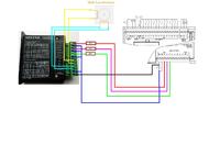
    First-Time Connection of Stepper Motor Driver: Verification of Wiring Diagram & Control from PLC

    1. Resistors limit the voltage from 24V to 5V. Which I do not know yet, because I do not know what current the input consumes. I will connect the power supply to the 5V output and measure the current and choose a resistor this way.
    2. The engine will be powered from 12V but it's not a problem, the converter will take care of the problem.
    3. Control from PLC is PTO or PWM?
  • ADVERTISEMENT
  • Helpful post
    #2 16299500
    vindevil
    Level 27  
    ad.1 Resistors do not limit the voltage, only the current. Correctly connected, provided that the resistance is counted to approx. 5 mA.
    ad.2 The inverter will not solve the problem.
    ad.3 Plc is to give PTO (although it can also be PWM, but it serves other purposes)
  • #3 16299528
    Paulo93
    Level 17  
    As for the first one, you probably meant voltage dividers, so definitely not as you gave them, because it will only limit the current, as your colleague wrote above.
  • ADVERTISEMENT
  • #4 16300544
    elektronikq
    Level 25  
    When it comes to resistors, they obviously limit the current but also the voltage in a sense. Instead of 24V put on the PULL input, it will put 5V because 19V will be put on the resistor but this is clear.
    Take 5mA or just take the power supply and put 5V on the pull and measure the current?

    Added after 2 [minutes]:

    Why doesn't an inverter do the trick? I just want to supply 12V because the engine is 12V.
  • Helpful post
    #5 16301630
    vindevil
    Level 27  
    There are LEDs in the optocouplers in the driver. Therefore 5mA.
    Resistors will lower the voltage by limiting the current, and this will be deposited as heat.
    It is very likely that there will be insufficient power on the motor with a 12V power supply.
  • #6 16302042
    elektronikq
    Level 25  
    The motor has 12V, that is its rated voltage.
    I have a question. If I give DC voltage from the 5V power supply to pull + and pull - and connect the motor, should I spin at maximum speed?
  • ADVERTISEMENT
  • Helpful post
    #7 16302209
    pafciowaw
    Automation specialist
    You must apply pulses to the pull input - each pulse is one step (or part if you set the controller to 1/2, 1/4, ... step)

    Added after 3 [minutes]:

    You can power the motor (stepper driver) with a much higher voltage than 12 V, while the driver has a current limit selected with jumpers - set to a low current - you can also power with 24 Vdc
  • Helpful post
    #8 16303441
    Ryszard49
    Level 38  
    Hello.
    Start by checking (on the controller housing) what voltage this controller is dedicated to.
    Greetings.
  • #9 16304595
    elektronikq
    Level 25  
    DC 9-40V - as shown on the controller

    Added after 3 [hours] 47 [minutes]:

    As for the motor, it is a bipolar motor: 12V 0.5A. A step size of 1.8 degrees or 200 pulses and it will do a spin.
    I have a current 0.6A on the controller and 0.9A in peak. So is this value too high, so the inverter remains? The engine will not be overloaded because it will work under light load. So I understand that in this configuration, the driver will give a maximum of 0.9A and in the working state of 0.6A, if the engine needs it. The more I charge him, the more he will want more and 0.6A will become dangerous. Use some simple security?
    Will the motor lose steps at In current?

    Added after 4 [minutes]:

    As for the resolution, I have the least microstep: 2. So it will divide my step by 2.
    Will it turn out 400 pulses then is a turn?

    I had such a simple idea. Make such a simple PWM with 50% duty cycle for example a timer. 5V amplitude and signal every 1s 1s break, i.e. 2s period. Connect the output to PULL + and PULL - to 0V, After 800s the motor would make a full turn?

    Sorry it's so trivial but this is the first time I do it and I just want to have fun and feel what I'm doing, then I would switch to quick exits.
    The question is whether I will not damage the driver :( ?


    --------------------------------------
    A colleague from the forum wrote that the stepper motor must be powered from the power supply from unstable voltage. Unfortunately, I do not have one, can I use the same 24V DC switching power supply that supplies the PLC controller to control the motor? However, is it powering the PLC and the motor from other sources? I have two 24V 1A impulse power supplies, but I do not have a non-stabilized power supply and no elements to assemble it.
  • #10 16304983
    vindevil
    Level 27  
    From what I have read, the driver can be supplied with voltage up to 40 V, so 24 from the stabilized one will be ok (the current must be correspondingly higher). I would also not worry about the motor current because there are jumpers settings for 0.6 Amp.
    And for checking, such a 555 timer will be perfect.
  • #11 16305101
    elektronikq
    Level 25  
    As for jumpers, the raised position is OFF. There was a down arrow on the DIP SWITCH and ON so up is OFF, that's what I set.

    I did a simple test: 24 DC power supply to GND and VCC. And on PULL + 5V and on PULL 0V.
    I connected the engine. I turned on the power after that, the 5V power supply and touched the pull + input (I was doing the pulse generator) and the motor was slowly turning. As I stated on DIR + from the 5V power supply and on DIR - 0V, the motor started to spin the other way.

    Most importantly, I connected the controller the other way around and the controller also experienced such information. The engine squealed then and was on the brake. When I switched off the power correctly, the motor was on the brake but it was quiet.
    The current consumed by the pull input reached 12.5mA, so at 10mA, i.e. from 24V, I will give about 2.2k? and it will be fine.

    Added after 22 [minutes]:

    Is it hard to handle PTO on the S7-1200?

    Added after 1 [minutes]:

    Can I, as I wrote earlier, make a simple generator on a PLC, e.g. on a timer, e.g. a pulse every 0.1 s.
  • ADVERTISEMENT
  • Helpful post
    #12 16306804
    pafciowaw
    Automation specialist
    If you have a PLC, don't have to build a generator. With the PLC you can set both the speed and execution of a sequence of step cycles, or reaching the intended position (virtual drive) - then get it :)
  • #13 16307315
    elektronikq
    Level 25  
    pafciowaw wrote:
    If you have a PLC, don't have to build a generator. With the PLC you can set both the speed and execution of a sequence of step cycles, or reaching the intended position (virtual drive) - then get it :)


    Okay, I get the PTO output. Should I make one axle? understand that one motor is one axle.
    Pafciowaw but on a simple generator would the engine also run?
  • Helpful post
    #14 16307405
    pafciowaw
    Automation specialist
    Yes ... it will "spin"; in the case of mass production of a "toy" based on a stepper motor, the use of PLC is not profitable and the manufacturer would probably use a generator on a prock; but in automation, the accuracy of positioning also counts, the possibility of using sequences (e.g. speed grading), adjusting the dynamics of motion to the inertia of the system - all this cannot be done with a simple generator. This is why the NC control to the PLC was implemented in order to be able to quickly and efficiently make various applications.
  • #15 16311520
    elektronikq
    Level 25  
    Alright just reading about PTO in Siemens. I just need MC_Power and MC_Jog block or should I add any other?
  • #16 17550863
    elektronikq
    Level 25  
    MC power and MC Jog made it possible to unleash the engine driving. Thank you.

Topic summary

The discussion revolves around the first-time connection of a stepper motor driver to a PLC, focusing on verifying the wiring diagram and control methods. Key points include the clarification that resistors limit current, not voltage, and the importance of measuring current to select appropriate resistors. The motor operates at 12V, and while a converter was initially considered, it was noted that the driver can handle higher voltages (up to 40V). Control methods from the PLC can utilize either PTO or PWM signals, with the consensus leaning towards PTO for step control. The user successfully tested the setup, confirming that the motor spins in both directions with proper input signals. The discussion also highlights the advantages of using a PLC for precise control over simple generators in automation applications.
Summary generated by the language model.
ADVERTISEMENT