logo elektroda
logo elektroda
X
logo elektroda

Adam turntable crazy revolutions - GS 420 linear drive problems

marekwaudio 9750 10
ADVERTISEMENT
Treść została przetłumaczona polish » english Zobacz oryginalną wersję tematu
  • #1 16484377
    marekwaudio
    Level 10  
    For several days I have been fighting with my friend Adam and the eternal problem of the unavailability of systems, parts, etc. returns. I know that everyone would like to have the maximum of the original, but it can't be slow. Maybe we could somehow try to develop new electronics on modern elements. I have DTRka with the principle of operation, my repairs and constructions at the nape of the neck, maybe too small workshop (equipment), and certainly many of us here have knowledge and possibilities. Develop a 60KHz generator, control that receives sensor feedback and drive amplifiers. The question is whether the mechanics is good, etc., because it was too expensive, but the costs and time are unknown, although everything is done to keep it alive. You can change everything until you drop, although the storage loungers can also be freed and the cash register goes. Someone is coming in? Let's talk, nice design, but it can change his guts. I am in contact with several people, somewhere else for nightmare money in relation to quality and certainty, you can buy something, only you lose energy and enthusiasm, faith. This could be resolved once and for all.
    Contrary to appearances, Adam is not a construction of Polish technical thought, but a clone of Fisher MT 6225, even a similar appearance. Fisher's electronic components are still quite accessible, after similar driving coils and particularly sensitive coils of the rotation sensor (300 turns of DNE 006 or about 3 meters 007 as you prefer and have possibilities, in home conditions almost impossible to rewind on these micro cores).
    If someone has Adam acting, let him take care of him, although the mechanics are not of the first quality (fold-out bearing), thin rods, limit switch that often falls (not like others on photo elements). Currently, launching quite rigid out of existence costs about PLN 400 + insert, and maybe a completely new drive regardless of the originality of the elements from the collector's point of view - it could be better.
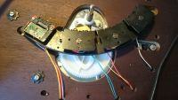
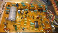
    My problem changes over time. I purchased the entire power package (stator coils with a working sensor). Symptom at the beginning, the strobe lights up and displays the speed digit (i.e. the limit switch works), the plate stood. Changing all these coils has activated the grandfather, but now it accelerates to the max and does not respond to speed regulation (change of generator voltage). UL1111 replaced on the board, the voltage on the old one did not hold, now OK. On an old stator and a damaged 1111, the voltages at the 1403 outputs were book-based, now they have dropped to about 6.5 V - 7V, if they can be stabilized at the same level (I cannot now set zero prams at the inputs). It seems that the system is waking up. I replaced the solid capacitors in the generator, the power supply also replaced many old ones is also good. Well, the money went and you would have to replace the working board in its entirety because some magic does not make technique, it flows ...... and it is not worth replacing all discreet parts because it will come out at the same price (currently one 1403 costs about 50 zlotys UL1111 about 1.5 for a change, and probably once 1403 also cost so much). .
    Anyone have any ideas ??? Adam turntable crazy revolutions - GS 420 linear drive problems Adam turntable crazy revolutions - GS 420 linear drive problems Adam turntable crazy revolutions - GS 420 linear drive problems Adam turntable crazy revolutions - GS 420 linear drive problems Adam turntable crazy revolutions - GS 420 linear drive problems
  • ADVERTISEMENT
  • #2 16485095
    aaanteka
    Level 42  
    Check that the transistors in this removed and new UL 1111 are functional. In general, these systems in their glory years showed a high failure rate. Currently, the alternative is to use 5 pieces of good quality transistors, e.g. The differential amplifier can additionally be thermally coupled with a piece of copper plate, if necessary. It is also possible to use SMD transistors and an appropriate adapter plate.
    After all, UL1403 circuits are ordinary low frequency end stages and can therefore easily be replaced by cheap commonly available monolithic power amplifiers (TDAs).
    In your case, however, it looks like they are in working order.
    I have the impression that you do not fully understand how this system works and what the individual system components are for (analyze your description from the instructions).
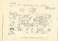
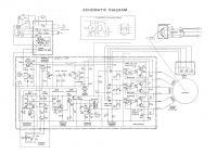
    It is most reasonable to make a detailed diagram with the drawing of individual UL 1111 transistors and a description of individual UL1403 PINs.
    Designs of turntables are quite similar but not one is a replica of the other, it was just in those days such electronic systems were implemented before specialized systems used in video or CD drives appeared.
  • ADVERTISEMENT
  • #3 16486910
    marekwaudio
    Level 10  
    But I understand and everything is written in the technical and technical documentation which I have attached and the control is drawn there, the description of the interior 1403 is also known. However, the drive coils and sensor are unstable enough that the rest cannot follow. 1111 I exchanged 3 items and I was also thinking about the discrete version because I already have a base. Like functional elements, but whether the scattering or the drawn design, the mixture of old and new parts is disappointing
    Until now, despite the knowledge, no one has done an alternative system, this applies to the post and I admit that I do not have an oscilloscope and maybe too little workshop in the broad sense of the word
  • #4 16486943
    Krzysztof Kamienski
    Level 43  
    Gentlemen! The whole system is an archaic ancestor of the BLDC motor, three-phase with inductive sensors (also three), made "on foot". Today this whole diagram is housed in one integrated circuit and works without additional rotor position sensors. This is about modernization. And if someone wants to go towards an almost complete "original", then it always remains to replace the inductive optical sensors (reflective optocouplers) and stick three pieces of aluminum foil inside the plate as a mirror for optical sensors.
  • ADVERTISEMENT
  • #5 16487090
    aaanteka
    Level 42  
    Unfortunately, the use of optical sensors is retardation, not progress.
    Induction sensor is one of the most reliable devices, which is why it is so widely used in industrial automation.
    As you progress, use a Hall sensor (halotron).
    Examples of integrated projects are BA6435S, BA6439P, HA13403, HA13409, AN3826NK, M56730, M51712FP.

    Feedback in such a system (where we care about precise speed control) is necessary and always used today.
    Back electromotive force measurement not requiring additional
    sensors more and more commonly used are not entirely suitable for this application.
    The construction may be elementary, but functional, and it works well in this particular application until today, in the era of throwing microprocessors into everything where they are unnecessary.

    On the other hand, a very good school for beginners.
  • #6 16487293
    Krzysztof Kamienski
    Level 43  
    aaanteka wrote:
    As you progress, use a Hall sensor (halotron).
    In fact, I forgot my head against the wall, deduct my points! :cry:
  • #7 16487325
    pikarel
    Level 38  
    My advice on how to deal with damage location:
    desolder T104 supplying the generator
    - attach the regulated power supply enabling adjustment in the range from 5 V to 10 V and set 10 V at the point after the collector
    - after reaching the RPM (too high) reduce the voltage supplying the generator
    If the rotation decreases and with difficulty, but you can set the speed on the strobe - then the power and control system is in working order. With this test, automatic rotation control does not work, because the generator supply voltage is given "from a finger."
    I suggest replacing all transistors BC 148 and BC 158 with modern equivalents:
    - npn on BC 548 B
    - pnp on BC 558 B
    Instead of UL1111, also solder the appropriate BC 548 B replacements directly into the holes on the integrated circuit feet, according to the internal UL1111 diagram.
    The transistors are so placed in the circuit that substitutes are easy to place in the place of the integrated circuit.
    For some it is a "babranko", but the conversion with a head looks quite aesthetic, and faulty BC 148 and BC 158 are noise generators similar to pea sprinkling.
    Good luck.
  • #8 16488298
    marekwaudio
    Level 10  
    The system has been repaired. According to the receipt from the store, a 680nF solid capacitor in its place gave old stock. Unbelievable in the meter, the nówka has a pair of pico. Or maybe someone threw a different one, it did not occur to me, Only its size is different but it is also 63 and not 400 V.
    Zeros at the entrances fixed. On 1403 outputs at 7.3 V which is the only deviation from the instructions but they are the same. Turnover adjusted by PRkami.
    Ladies and gentlemen, this doesn't change the fact that a new Adam / Adamek electronics board could be useful, because this is the last time when you have something in the drawer ....... stocks will run out sometime. I heard cool ideas, I would like to know such a system integrating similar "automation" in the cube, cubes, instead of building a challenger on foot :)
  • ADVERTISEMENT
  • #9 16489096
    pikarel
    Level 38  
    marekwaudio wrote:
    System repaired (...). On 1403 outputs at 7.3 V which is the only deviation from the instructions but they are the same (...)

    If the voltage at the outputs (n.11) is half the power supply (n.12) - it is very good.
    To make sure, add a second 1000 uF to the C125 capacitor for the test, and if it does not change anything - then leave it this way.
  • #10 16489246
    marekwaudio
    Level 10  
    I even exchanged the whole conduit for 2200, it doesn't change anything, the voltage at the outputs is not half the power supply, it was true on old coils, their measured resistance is similar, but maybe the components of other impedances are different. It works normally so it's better not to move. Maybe less "power", less heating, it will last. Today I will finish the mechanics and in future I think about a completely new solution at the beginning.

Topic summary

The discussion revolves around the challenges faced in repairing and modernizing the Adam turntable, specifically the GS 420 model, which suffers from issues related to its linear drive system. Participants suggest various solutions, including checking the functionality of transistors (UL 1111, UL 1403), using modern equivalents (BC 548 B, BC 558 B), and considering the integration of new electronics to replace outdated components. The conversation highlights the potential for developing a new electronics board to improve performance and reliability, as well as the importance of feedback mechanisms for precise speed control. Suggestions include using Hall sensors and integrated circuits for modernization, while also acknowledging the limitations of existing components and the need for a more robust design.
Summary generated by the language model.
ADVERTISEMENT