logo elektroda
logo elektroda
X
logo elektroda

Troubleshooting Crawford ECS930A + CDM9 Automation Drive: Motor Not Responding

lz11980 48468 60
ADVERTISEMENT
Treść została przetłumaczona polish » english Zobacz oryginalną wersję tematu
  • #1 16172187
    lz11980
    Level 19  
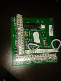
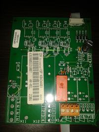
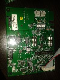
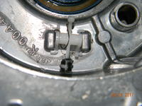
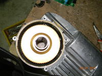
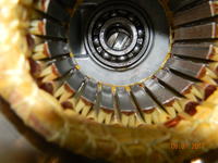
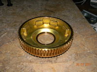
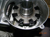
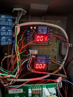
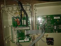
    I will refresh the topic ECS930A CDM9 driver, 3 plates in the cheesecake + 2 in the engine, the drive does not move in any way after pressing the up / down button there is no reaction on the plates, after switching on the power supply on plate No. 1 two red RXD and TXD LEDs are blinking relatively steadily , adjusting the potentiometers T1 and T2 to a minimum does not help (they are responsible for the time of auto closing and lighting of the lamp), on board No. 3 after shorting contacts 12-13 to x1, two yellow LEDs from the crimp strip sensor light up, after switching SW1 on it lights up red diode, but pressing the bottom button and the crimp bar does not start the engine, I assume that the motor should have an additional switch on the rotation of the clutch lock, but I cannot remove the inverter plate. I also assumed that on board No. 2 on connector X13 should be shorted 1-3 (anyway, opening does not help) is responsible for blocking the opening. in the 4th picture everything is connected, instead of a pressure sensor I connected an ordinary switch. Troubleshooting Crawford ECS930A + CDM9 Automation Drive: Motor Not Responding Troubleshooting Crawford ECS930A + CDM9 Automation Drive: Motor Not Responding Troubleshooting Crawford ECS930A + CDM9 Automation Drive: Motor Not Responding Troubleshooting Crawford ECS930A + CDM9 Automation Drive: Motor Not Responding
  • ADVERTISEMENT
  • #2 16172899
    damek_2009
    Level 2  
    Hello

    I understand that after removing the power and reconnecting the motor does not start. Blinking red LEDs are from the photocells this is the correct symptom. Contacts 12-13 NO pulse input - close as I remember correctly. The yellow LEDs are from the pneumatic sensor, they should be lit all the time and after pressing the seal go out and after a while light again. Does the engine start after switching SW1 and pressing the button? To remove the inverter board, unscrew the two barely visible screws on the motor housing for an allen key or torx key, then gently pull the plastic white latches away and remove the plate. You should also check the keyboard tape - often thin paths interrupt especially in wet rooms (car washes etc.), the stop switch will definitely close. There should be a jumper between pins 9-10.
  • ADVERTISEMENT
  • #3 16173259
    lz11980
    Level 19  
    The jumper 9-10 is on, the red diodes are flashing regularly, the pneumatic sensor is replaced with a switch, after turning on sw1 on ON the red diode next to 2 yellow lights up the reaction to pressing up the red diode goes off until I keep pressed the button on the housing to press the button down there is no reaction, it was possible to pull the inverter out of the housing, the plates are clean without blinding, it turns out that there is only a thermal sensor at the end of the plate, 3 wires go to the motor: black, red and brown, now the question is whether it is a 1 or 3 phase motor , the puzzle is because on the rectifier bridge on the inverter board on the 2 middle contacts is 230V while on the external is 725V (I checked 3 times), and on the board with the orange relay there is a green diode which also does not react is looking at the paths signaling the operation of the relay from external opening lock. Interestingly, I have 2 the same sets of control panels and both behave the same, tomorrow I will arrange to do an additional motor with the control panel power supply and inverter, if the motor is single phase, I tend to use the usual control panel for the motor from a sliding drive I would only add limit switches and should , yes I have rewritten the wa100 control.
  • #4 16177980
    lz11980
    Level 19  
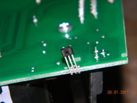
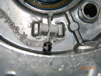
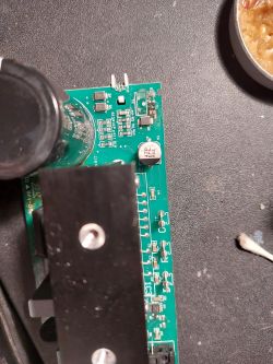
    After a whole day of spinning up the engine and comparing it to the working one, the conclusion is that the engine does not work because of the drive disengagement sensor, but that it was not easy it turned out after completely dismantling the transmission that it is a magnetic sensor so probably hall has such markings: A 20E 0948 049A , placed on the inverter board, while in the gearbox the magnet is pivoted, which through the aluminum casing is to act on it as the drive is disengaged and disconnect as it is disengaged. I worked on the sensor (after removing the electronics from the housing and the initial assembly of the engine from the gearbox) with a magnet (I had a magnet on the disassembled disk on hand), and it works, i.e. it turns in both directions, I was looking on the Internet, but I can't find such a magnet from the old drive, so tomorrow round after electronics, and unfortunately to remove the engine had to physically act on symering so further assembly tomorrow. when I'm done I will try to post a few photos from crawford drive demolition stages for posterity. the photo shows both a sensor and an unlucky magnet. Troubleshooting Crawford ECS930A + CDM9 Automation Drive: Motor Not Responding Troubleshooting Crawford ECS930A + CDM9 Automation Drive: Motor Not Responding
  • Helpful post
    #5 16194578
    lz11980
    Level 19  
    For posterity and curious how Crowford "1m" looks like inside, disassembly instructions for the 1M Crawford geared motor:

    1.Unscrew the electronics cover on the 3x trox engine,
    Troubleshooting Crawford ECS930A + CDM9 Automation Drive: Motor Not Responding
    2. Detach the ground from the motor (slide with latch)
    3. Unlock the plastic white latches and carefully disassemble the inverter board by pulling out, and you have to unscrew the 2 screws from the outside that hold the heat sink of the inverter.
    Troubleshooting Crawford ECS930A + CDM9 Automation Drive: Motor Not Responding Troubleshooting Crawford ECS930A + CDM9 Automation Drive: Motor Not Responding
    4. Remove the motor terminals, 3 black, red and orange cables
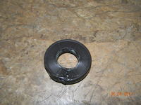
    5. Unfasten the spring holding the engine cover, disassemble the black toothed disc from the rev counter (it is push-fit so gently) and forcefully remove this cover, I did it with a hexagon and walrus pliers additionally using a hammer
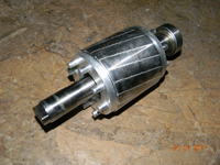
    6. Now, unfortunately, we also have to force the impeller out of the bearing, it's hard but it will manage
    Troubleshooting Crawford ECS930A + CDM9 Automation Drive: Motor Not Responding
    7. Forcibly and unfortunately with damage (no approach) we have to remove the motor shaft symmetry, therefore with the symmetry there is a spring-loaded bearing protection (seger) which was pulled out with 2 screwdrivers and a hook
    Troubleshooting Crawford ECS930A + CDM9 Automation Drive: Motor Not Responding
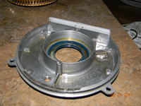
    8. Unscrew the 4x torx gear cover, gently beating from the bottom with a screwdriver so as not to damage the O-ring on the cover and do not spill oil, lift the cover, come off the bearing or not (the bearing must be removed anyway)
    Troubleshooting Crawford ECS930A + CDM9 Automation Drive: Motor Not Responding Troubleshooting Crawford ECS930A + CDM9 Automation Drive: Motor Not Responding
    9. Now, gently turning the transformer wheel we must knock out the worm shaft with the bearing (otherwise it will not be possible to disassemble the worm wheel)
    Troubleshooting Crawford ECS930A + CDM9 Automation Drive: Motor Not Responding
    10. For me, it was not necessary to knock out the motor bearing completely, it was enough for the shaft to jump out of it, which allows you to tilt it and remove the gear
    Troubleshooting Crawford ECS930A + CDM9 Automation Drive: Motor Not Responding Troubleshooting Crawford ECS930A + CDM9 Automation Drive: Motor Not Responding
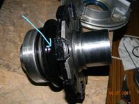
    11. After removing the coupling with the shaft we have a visible swing out element with a magnet
    Troubleshooting Crawford ECS930A + CDM9 Automation Drive: Motor Not Responding
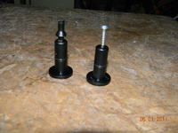
    12. It is worth checking and replacing the O-rings on the decoupling mushrooms (the photo shows how the element is made)
    Troubleshooting Crawford ECS930A + CDM9 Automation Drive: Motor Not Responding
    13. Fold in the reverse order.
    14. it should be noted that the wide sleeve bushing snags onto the clutch sliding disk, otherwise there is no release
    Troubleshooting Crawford ECS930A + CDM9 Automation Drive: Motor Not Responding

    Added after 2 [hours] 21 [minutes]:

    And some more materials, the only ones that have been found on the Internet, maybe someone will be useful
  • ADVERTISEMENT
  • #6 16213494
    lz11980
    Level 19  
    Apparently everything is ok but I need to change the direction of rotation of the motor, the power supply is 230V from the inverter comes out of 3 phases on the stator winding, and now when I move the 1 wire it turns in the opposite direction but with much less force, unfortunately Crawford is such a secret company that does not provide any information beyond the fact that their service can be arranged, and thus PLN 500 for arrival + extrasy, anyway, calling their service outside the hotline is already a feat ... Maybe someone has already combined with the change of turnover at Crowford 1m Cdm9 930A,
  • ADVERTISEMENT
  • #7 16253822
    lz11980
    Level 19  
    This is the end, both engines work though not quite as I would like ...
    In one control, the automatic closing function blocked despite all DIPs and potentiometers on OF, unfortunately it was not possible to determine how to change the direction of rotation of the motor so I was forced to change the method of mounting the motor, but as for a gate and gearmotors with at least 10 years of experience they work great and much nicer than e.g. the new Wiśniowski.
    The way of programming the road is this: set the gate about 150 cm from the floor, turn the SW1 switch next to the red LED to ON, move the gate to a position about 100 cm above the floor, press the bottom gasket so that the yellow LEDs go out after pressing the arrow down, the gate should drive down to the floor and then from the machine up to the buffers and stop. IMPORTANT if there is no floor, there must be something in the light of the gate so that the pneumatic seal works, otherwise the gate will not know when to stand. Then we switch SW1 to OFF and now after pressing down the gate should go down and up and at the end,

    At the end I will only add that I lost a lot of time to talk to someone from Crawford Polska or ASSAABLOY but it turned out that either they have no idea about this drive or they do not want to help because they earn on websites and can offer me a service from Warsaw to Warsaw direction of rotation adjustment. Of course, they have not confirmed that the service technician will have the concept of this drive !!! payable anyway for arrival. They are all so secret that they are forbidden to provide other numbers as on the hotline to arrange service, there is also no way to find out about spare parts because their service technicians will arrive to determine what is damaged and then they will come back and repair it if necessary.
    In that case, I wish them good luck on our not-so-rich market and I will eventually get to know their secrets someday ;)
    For those interested, I can share this small amount of information that I have found on the internet up to CDM 5.9, 10 hcs
  • #8 18948523
    doortech
    Level 9  
    Hello. I might be able to help you out.

    Please follow these instructions:

    Installing & Starting to use the Control Unit

    NB The power shall be switched OFF-ON before an installation!

    1. Disengage the door, place it in a position of 1.5m above the floor and engage it. Switch on the power.
    2. Mark out a “1m position” above the floor on the door track
    3. SW1 “ON”.
    4. Hold-to-run downwards (Up- or Down button) until the rubber sealing edge is in position with the 1m mark. (Adjust with Up/Down buttons). The door is now stopped at the mark.
    5. Squeeze the rubber sealing hard with your hand in a short pulse, then release. The LEDs D4 and D5 switch off shortly.

    VL Drum

    6. VL Drum (Full incline wire drum):Push Down. The door moves down to the floor and up to a fully open position.
    SL, LL & HL Drums

    7. SL, LL & HL Drums (Half incline- or straight wiredrum) Push Down. The door moves down to the floor and reverses. When the top section of the door is in the middle of the rail bend / or where the cable reaches the straight part of the drum, Push stop. Then push up. The door now moves to a fully open position.

    NB! If the installation fails between points 1-7, adjust the torque.

    8. SW1 OFF. The door is ready for operation after 2 seconds.

    Installation is now complete.

    How to adjust the Torque (Force)
    If the installation fails _during_ normal installation, do as follows:

    NOTE!
    The torque always starts the first time from the original factory setting, which is step 9 of 15.

    1. Switch off the power. SW1 and SW2 in OFF
    2. Disengage the door, plase it in a position 1.5 m above the floor and re-engage it.
    Switch on the power. SW2 in ON. Put SW1 in ON, then back to OFF again.
    3. Hold the STOP button down and, at the same time, push;
    - the UP button once, for a stronger operator.
    - the DOWN button once, for a weaker operator.

    NOTE! Every push on the UP or DOWN button makes the operator stronger or weaker.

    4. The torque is now adjusted. Switch OFF the torque setting switch SW2.

    5. If the torque is still too weak or strong, repeat steps 2-4 again.

    ---

    The door should now be ready to use. If the drive goes down while pressing up on the display, this tells the control unit to swap phases automatically, and you should not need to worry about that.
  • #9 19018227
    mikumar
    Level 1  
    dear sir, madam,
    good afternoon This is Kumar from Doha Qatar.one of Crawford control board function is working well. but automatic close is not working .safety edge is working good photocell is working good but automatic close is not working , how to put automatic close please tell me, sir
  • #10 19206397
    roton
    Level 12  
    Good day.
    I allowed myself to connect to the topic because I see that you gentlemen possess almost secret knowledge. About 1 year ago I bought a gate, drive and control
    Crawford 1m. Everything comes from disassembly but was in perfect condition.
    The company from which I purchased the device installed and commissioned it. Everything worked reasonably well for a couple of weeks. There was a problem with closing the gate with the remote control. The approach fell on the pressure switch connected by a hose to the bottom seal. The seller sent a service technician who played with the switch and the switchboard. Everything worked again for a few days. However, with the passage of time, operation of the gate became more and more painful. On command to open, the gate moves up automatically. Close command, gate runs automatically or does not move at all. A few open and close cycles are ok then no reaction. This is how it behaves on commands from the remote control.
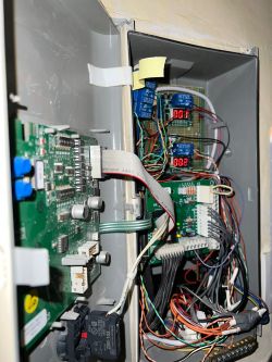
    The buttons are similar, with the difference that holding the close button goes as long as I hold the button. The gateway vendor stopped answering the phones, so I started to "PhD" myself from that gate. I can only say about Crawford that their attitude is disgusting and not to Polish reality. To the point. I checked the operation of the pressure switch very carefully and many times. I regulated its sensitivity and venting time. After each such intervention, the gate started to work properly, but only for a few or a dozen or so cycles. I have acquired a new pressure switch. After its installation, nothing changed. All this fun has led to another problem now showing up. When the gate automatically goes up and I press the STOP button, the gate stops but does not move again, neither down nor up. I have to figure it out, disengage the gate and lower it manually. After this combination, the gate works again, but only until the next STOP is pressed. In summary, I would like to reset all the programmed parameters and try to program the gate again. This may cause the hardware to function properly. I would also like to activate the automatic closing function after a preset time. Unfortunately, I haven't found any manual on how to do it. I am asking colleagues for help.
    Regards - Robert.
  • #11 19419101
    waldek418
    Level 7  
    The timer closing is activated by holding the stop, opening and closing together for 6 sec. After this time, release the buttons and a dot will appear on the display
    You set the time with the top potentiometer
  • #12 19936411
    dakin11
    Level 21  
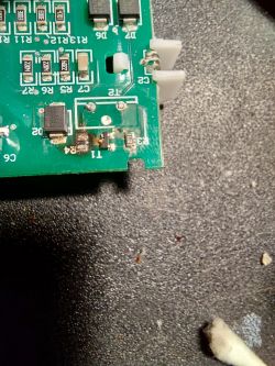
    Hello, I am writing to people in the topic if they would have information about damaged elements on the inverter board in the motor. The damaged elements are R4, T1, R3, T2 shown in the picture, unfortunately I am not able to read them because they were completely burnt. the inverter is in the CDM9 motor. Thank you in advance for the information Troubleshooting Crawford ECS930A + CDM9 Automation Drive: Motor Not Responding Troubleshooting Crawford ECS930A + CDM9 Automation Drive: Motor Not Responding
  • #13 19936466
    waldek418
    Level 7  
    Hello, is it a board with a transmission lock sensor (inverter) or a control board in the engine?
  • #14 19936483
    dakin11
    Level 21  
    It is motor power board (inverter)
  • #16 19951300
    dakin11
    Level 21  
    waldek418 wrote:
    Maybe it will help
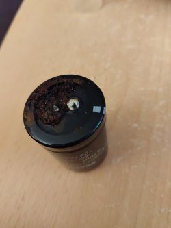
    Thanks very much, after replacing it works flawlessly, the cause of the damage was the electrolytic capacitor 470uF, it ran out. I have one more gate out of the 8 which displays E24 when lifting and makes noise as if the bearings have run out. I am waiting for a complete disassembly, plus I will replace the capacitor on the motor power plate.
  • #17 19951383
    waldek418
    Level 7  
    Hello
    E24 is not treated as an error, it is displayed after a voltage failure and loss of position. I would suggest checking the power supply for a voltage drop.
  • #18 19954599
    dakin11
    Level 21  
    After replacing the capacitor in the second drive, the error is no longer displayed. With this 24, I will agree that there is a power outage, and if there is a weak power supply, these were checked before repair, so the inverter on the table and to be replaced and solder improvement. The operation brought a positive effect, the gate moves even much better and stops at the threshold. In the case of this drive, the fault 24 appeared in different positions of the gate and at that moment it stopped, it reset when it went completely up, it appeared even when it stood in the upper and lower position after stopping the calibrated position. There are 8 gates on my website, 6 of which have already completed 35,000 cycles within 8 years. The service was coming and they did not know what to do with it, they changed the rollers, seals, adjusted the pressure, adjusted the springs, and finally suggested replacing the cassette plus the engine, and then I went to work. In the photo, the capacitor I replaced speaks for itself. Troubleshooting Crawford ECS930A + CDM9 Automation Drive: Motor Not Responding
  • #19 19954678
    waldek418
    Level 7  
    welcome back
    I return my honor, it has been slightly disturbed by the tooth of time.
    If there is anything you need, please go to priv.
  • #20 20089215
    etang789
    Level 1  
    Troubleshooting Crawford ECS930A + CDM9 Automation Drive: Motor Not Responding Troubleshooting Crawford ECS930A + CDM9 Automation Drive: Motor Not Responding

    I don't know why my contractor did this to repair my garage door. Now I have no idea how to fix this and want to change to another brand of operator completely!

    Problem is I have center motor and there isn't much other option!
  • #21 20303549
    doortech
    Level 9  
    etang789 wrote:
    Troubleshooting Crawford ECS930A + CDM9 Automation Drive: Motor Not Responding Troubleshooting Crawford ECS930A + CDM9 Automation Drive: Motor Not Responding

    I don't know why my contractor did this to repair my garage door. Now I have no idea how to fix this and want to change to another brand of operator completely!

    Problem is I have center motor and there isn't much other option!


    What the hell! That is not a fix -- That is a hack.
    Please PM me more photos of this, as I am curious to see what they did, and might be able to help fix the core issue that this is trying to. Wow.
  • #22 20344977
    tomekzawadzki20
    Level 4  
    Hello, I would like to get information because I have a Crawford 940 gate, everything works fine, until one day no buttons work either up or down, after holding down the stop button for a long time, it shows error E08
  • #23 20346372
    doortech
    Level 9  
    E08 is emergency stop.

    Check all stop circuits, including the one in the engine.

    What has changed since last working?

    X7 - 2&3 NC
    X2 - 3&4 NC
    X3 - 1&2 NC
    X4 - 1&2 NC Push button in controller lid
  • #24 20357471
    tomekzawadzki20
    Level 4  
    Hello, since the last job it has changed that the gate just closed normally and the next day the chapel after disconnecting the engine with the possibility of manually opening the gate, error E24 and E08 popped up and when it comes to circuits, they are all OK
  • #25 20380315
    carla
    Level 12  
    Hello
    I have a problem with the Crawford ECS 950 gate, CDM9 drive, E14 is lit on the display and the engine does not start. After switching SW1, E05 is lit, the engine does not start.
    Does any of you esteemed colleagues know what this error means? Where to look for the cause?
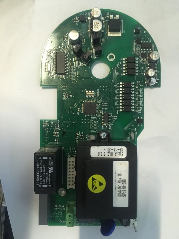
    I managed to read IC13, PIC18F2520 on the K047620 Rev:A board
    Does anyone have a batch for PIC16F76 and PIC30F5015 on the board (from the photo) )K0044150 Rev:A


    Troubleshooting Crawford ECS930A + CDM9 Automation Drive: Motor Not Responding
  • #26 20381371
    ethstorey
    Level 1  
    Is there any way to reset the service light on these panels once the limits are set?
  • #27 20381421
    doortech
    Level 9  
    ethstorey wrote:
    Is there anyway to reset the service light on these panels once the limits are set?


    Not without Crawford's service tool.

    Added after 3 [minutes]:

    carla wrote:
    Hello
    I have a problem with the Crawford ECS 950 gate, CDM9 drive, E14 is lit on the display and the engine does not start. After switching SW1, E05 is lit, the engine does not start.
    Does any of you esteemed colleagues know what this error means? Where to look for the cause?
    I managed to read IC13, PIC18F2520 on the K047620 Rev:A board
    Does anyone have a batch for PIC16F76 and PIC30F5015 on the board (from the photo) )K0044150 Rev:A


    Troubleshooting Crawford ECS930A + CDM9 Automation Drive: Motor Not Responding


    E14 is internal daughter board error. No specifics on what it really boils down to.

    Service manual says to replace motor logic.

    Personally, i think it is a fault on the encoder.
  • #28 20384972
    carla
    Level 12  
    After programming with the ECS_950_R16 batch (It can be EEPROM itself, PIC18F2520), the service lamp on the K04720 board goes out.
    After completely desoldering the ic5 HC14NG on the processor card, the engine started and the E14 error disappeared. The engine worked both ways
    after pressing the keypad buttons, but after a few minutes it stopped responding. After soldering the system back, E14 lights up. No reaction. Is Encoder on PIC16F76?
    I have two drives with the same E14 error and thus little room to maneuver with substituting elements.
    Does anyone have a full batch to program the PIC30F5015?
    Programowa...e_CDM9.rar Download (113 bytes)
  • #29 20451182
    juhokuuru
    Level 1  
    Hello. I have problems with Trouble Shooting Guide
    (all types)
    CDM 9
    ECS 920, 930, 950
    Installation.

    I want to know how the initial installation works step by step.
    Can somebody help.
    I know that sw1 has to be turned on, but which dip buttons do I raise to the ON position?
    Thank you.
  • #30 20451477
    doortech
    Level 9  
    For the DIP-switches S1, S2 as well as for the potentiometers T1 and T2
    Switch Description
    S1:1 ON Gives 50 000 cycles on the reset-able cycle counter
    S1:1 OFF Gives 20 000 cycles on the reset-able cycle counter
    S1:2 ON Gives that the interlocking relay (X13:7-8-9) indicates all errors except E08
    S1:3 ON Gives flashing red light between the limit positions. (Only at warning lights, not at traffic
    lights.)
    S1:3 OFF Gives steady red light between the final limit positions. (Only at warning lights, not at
    traffic lights.)
    S1:4 ON Gives red light at fully closed door. (Both at warning and traffic lights)
    S1:5 ON Gives flashing red light before automatic closing (T2)
    S1:5 OFF Gives red light before automatic closing (T2) (S1:5 ON and OFF are only valid at warning
    lights not at traffic lights)
    S1:6 ON Disengages Open Outside command at traffic lights for 10 seconds in order to avoid
    unwanted activation from, for instance, outer magnetic loop on the way out
    S1:7 ON Gives direction sensing traffic lights(controls opposing traffic by red/green lights)
    S1:7 OFF Gives indication (230V) door moves up (X12:3) and door moves down (X12:4) on the SCR-
    PCB- For the kits D1-D4 and D7.
    S1:8 ON
    Gives FR-function. (All commands except safety are delayed 2.5 seconds while warning
    lights are flashing). At automatic closing T2 is replaced by the 2.5 seconds. At Traffic
    Lights one gets a steady light during T2

    ---

    S2:1 ON Gives DK-function (The Door(Operator) goes always over into dead-mans grip down if the
    safety edge has been activated
    S2:2
    Is used to set the position for reduced opening. Put the door in the desired position, put
    the switch ON-OFF. Change-over switch in the lid for fully open and reduced position.
    Photocell mandatory for automatic closing
    S2:3 ON Automatic closing after passing of the safety photocell. Can be combined with S2:5 ON.
    S2:3 OFF Automatic closing from fully open door.
    S2:4 ON
    Doubles the adjusted time on T1 if no acknowledgement has been given, and cuts it by
    half if acknowledgement is given. Both the safety photocell and additional safety are able
    to give acknowledgement.
    S2:5 ON Automatic closing after additional safety, connected to X8:5-6, has been activated. NOTE!
    Additional safety is working with a normally open contact (N-O).
    S2:6 ON Memory (open) to an interlocked door. If an interlocked door is goven an open command,
    it will store this and open when it is not interlocked anymore.
    S2:7 ON Gives 1-900 seconds on T1
    S2:8 ON

    ---

    NB The power shall be switched OFF-ON before an installation!

    1. Disengage the door, place it in a position of 1.5m above the floor and engage it. Switch on the
    power.

    2. Mark out a “1m position” above the floor on the door track

    3. SW1 “ON”.

    4. Hold-to-run
    downwards (Up- or Down button) until the rubber sealing edge is in position with the 1m mark. (Adjust
    with Up/Down buttons). The door is now stopped at the mark.

    5. Squeeze the rubber sealing hard with
    your hand in a short pulse, then release. The LEDs D4 and D5 switch off shortly.

    VL Drum
    6. Vertical Lift Drum (Full Stigningstrommel):Push Down. The door moves down to the floor and up to a fully
    open position.

    SL, LL & HL Drums
    7. Standard Lift, Low Lift & High Lift Drums ; Push Down. The door moves down to the
    floor and reverses. When the top section of the door is in the middle of the rail bend / or
    where the cable reaches the straight part of the drum, Push stop. Then push up. The door now
    moves to a fully open position.

    NB! If the installation fails between points 1-7, adjust the torque.

    8. SW1 OFF. The door is ready for operation after 2 seconds

Topic summary

The discussion revolves around troubleshooting the Crawford ECS930A and CDM9 automation drive, specifically addressing issues with the motor not responding to commands. Users report symptoms such as blinking LEDs, lack of motor movement, and error codes like E04 and E14. Solutions proposed include checking wiring, ensuring proper jumper settings, and examining the inverter board for faults. The importance of the drive disengagement sensor and the need for specific components like the Hall sensor and capacitors are highlighted. Users also share experiences with programming the control unit and adjusting settings for automatic closing functions. Various troubleshooting steps, including measuring voltages and replacing faulty components, are discussed to restore functionality.
Summary generated by the language model.
ADVERTISEMENT