Elektroda.com
Elektroda.com
X
This content has been translated flag-pl » flag-en View the original version here.
  • Copy amplifier Rotel RA-820

    Hello, inspired by the designs presented on the forum, I decided to build my own amplifier, the project is strongly based on
    Mosfet 2x50W amplifier with atTiny driver and remote control the heart of which is a power amplifier copy of the Rotel RA-820.
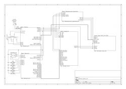
    The diagram of the whole is not as clear as I would like, but you can see what it is connected with.
    Copy amplifier Rotel RA-820

    Power amplifier
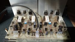
    Copy of ROTEL RA-820 or "hajend for the poor" on BD911 / BD912 transistors and here I have to mention my problems with this design. I managed to burn the power transistors twice, once setting the quiescent current and the second time connecting the signal source with the amp on, which was not the smartest thing. I got the impression that the system is very sensitive to mistreatment, according to front247 Poor quality transistors can cause these problems.
    Copy amplifier Rotel RA-820


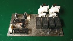
    Power Supply
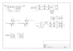
    The driver and preamplifier are powered by a small 2x9V 10VA transformer that is on all the time. The voltage is stabilized at +/- 5VA to power the digital potentiometer and the preamplifier circuit, additionally by a + 5VD choke to power the digital part and relays. Unfortunately, I underestimated the power lost on this stabilizer and had to put it on a separate heat sink outside the PCB. The relays consume 300mA, which with 9V put on the stabilizer gives 2.7W, it would be better to power the relays from 12V, then with stabilization you would lose only 0.26W

    A 2x27V 120VA transformer with two pairs of 10000uF capacitors was used to power the power amplifiers. Relay K1 turns on the power, and K2 closes the soft start resistors, both relays are controlled by the uC.

    The tile was designed so that it could be mounted vertically as in the project of my colleague Katakrów, but in the end I had no idea how to do it without using wood.
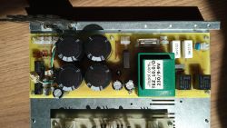
    Copy amplifier Rotel RA-820 Copy amplifier Rotel RA-820


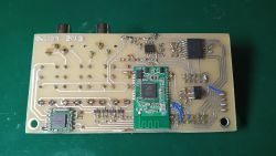
    Preamplifier
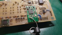
    The board with the input selector, digital potentiometer and radio modules allows switching between four signal sources, AUX 1, AUX 2, Bluetooth and radio. Bluetooth implemented on the XS3868 module is turned on only after selecting it as the source, you can jump between songs with the right / left buttons. I tried to change the name and password with uC, unfortunately to no avail. OVC3860 is a nice and cheap module, which can be used as a standalone module or with AT commands to change songs, volume, etc. but changing such a basic thing as the name requires a lot of effort, I do not understand why it could not be done from AT commands. Out of curiosity, I checked how much I gave the external antenna, without the RSSI -90 antenna, with the RSSI -55 antenna at a distance of 1m. FM radio on the TEA5767 module, the frequency is changed with the right / left buttons. The CS3310 digital potentiometer with a preamplifier and a set of filters is taken from the project of my colleague Katakrow, I only changed the amplifier to NE5532. The program does not use the chip amplifier section.

    The common ground for the digital and analog parts is the spout on the top PCB layer; I was not sure if it was a good idea, especially since the lack of space did not allow me to arrange the individual modules in an optimal way, but the whole thing works very well, I can not hear any interference from the digital part.
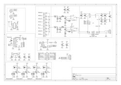
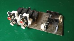
    Copy amplifier Rotel RA-820 Copy amplifier Rotel RA-820 Copy amplifier Rotel RA-820 Copy amplifier Rotel RA-820 Copy amplifier Rotel RA-820


    Speaker protection
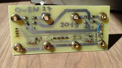
    DC component protection connected to the speaker output selector, banana connectors are screwed directly to the board. Unfortunately, sometimes the speaker connectors do not touch, the counter nuts are missing, it should be done as shown in the picture.
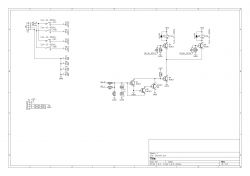
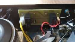
    Copy amplifier Rotel RA-820 Copy amplifier Rotel RA-820 Copy amplifier Rotel RA-820 Copy amplifier Rotel RA-820


    Controller
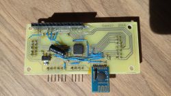
    The driver is based on the STM32F100C8T6B microcontroller, of course there is no need to use a 32 bit processor, I chose it to gain experience with STMs. There were plans for a remote control on NRF24L01 modules, which never happened. The blue OLED 16x2 display looks very nice, after two years I did not notice any burned-in pixels, so also a plus. The volume and I / O selector settings are stored in the built-in volatile memory with a 2032 battery, which eliminated the need to detect a power failure. There is terrible tinkering on the tile, it works but it looks disgusting, next time I would outsource it to a tile mill.
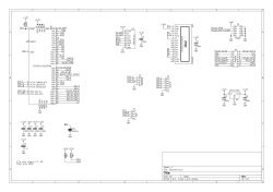
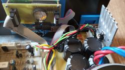
    Copy amplifier Rotel RA-820 Copy amplifier Rotel RA-820 Copy amplifier Rotel RA-820 Copy amplifier Rotel RA-820


    Housing
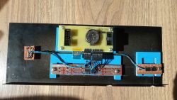
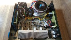
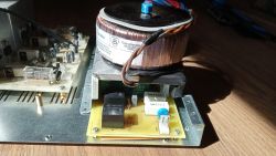
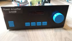
    T-268, it was tighter than I expected, the transformer had to be placed above the power supply board, there was nowhere else to go. The advantage of the housing is certainly its width, at 260mm it fits into narrow cabinets. The buttons and the potentiometer knob are made of PLA, together with the blue OLED they contrast nicely with the black casing.
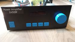
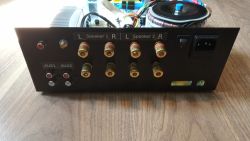
    Copy amplifier Rotel RA-820 Copy amplifier Rotel RA-820 Copy amplifier Rotel RA-820 Copy amplifier Rotel RA-820


    Summary
    The amplifier has been working without any major problems for two years, sometimes the program freezes and this is where the switch on the back comes in handy :D . More generally, the outputs of the processor are not even protected by resistors, and the signal strips run next to the power cables and output power amplifiers, strange that the processor is still alive. It is also worth adding ferrite beads on the uC power supply and modules on the preamplifier board. BT after some time without the paired device goes into some sleep mode, which cannot be woken up by the switch or the input selector, you need to use the main switch. It is possible that disconnecting the power supply with the transistor would solve the case, I don't know, I didn't check.
    After moving, he began to hum softly, he probably does not like the new apartment :)

    Cool? Ranking DIY
    About Author
    Owen27
    Level 11  
    Offline 
    Owen27 wrote 36 posts with rating 17. Live in city Gliwice. Been with us since 2008 year.
  • #2
    koko0
    Level 17  
    What was the security layout inspired by?
  • #3
    Owen27
    Level 11  
    Fragment of the unizab1 project, Link I just don't remember why I used two capacitors.
  • #4
    Baskhaal
    Level 18  
    1. The heat sinks of the power amplifier 'sit in the housing' with the airflow between the fins blocked (top and bottom), what temperatures do they reach at 50 and 100% power after five minutes?
    2. The front panel beats the eyes, the blue one ... ugh ... but ok, not everyone has to like it.
  • #5
    necavi
    Level 18  
    Quote:
    The buttons and potentiometer knob are printed from PLA

    Only the inscriptions embedded in them will collect dirt over time and there will be a problem with cleaning. Additionally, in combination with the sticker, the whole thing looks "workshop", but I have the same problem, the housings are usually unloved children of amateur electronics :wink:
  • #6
    katakrowa
    Level 22  
    Owen27 wrote:
    sometimes the program hangs and this is where the switch on the back comes in handy

    Congratulations on your persistence. As for the above, long signal / control connections between the boards make the circuit susceptible to hanging, e.g. during the operation of relays.
    High voltage pulses directed directly to the CPU pins are problematic. A good direction is the use of optocouplers. I understand well how much you do not want to do it when we are close to the goal, because although I already know this problem well, I have not equipped another board that I recently designed with these protections :-) Well, you see, laziness is stronger than reason and experience.

    It's great that you uploaded the source codes.
  • #7
    rosomak19
    Level 22  
    Hmm, 120 VA and soft start? You can, why not, but in this case an unnecessary circuit for such a low power.
  • #8
    tytka
    Level 21  
    Owen27 wrote:
    (...) on BD911 / BD912 transistors and here I have to mention my problems with this design. I managed to burn the power transistors twice, once setting the quiescent current and the second time connecting the signal source with the amp on, which was not the smartest thing.

    Well, I would not try to copy the Rotel on these transistors. One that in my opinion they are not suitable for this at all, and two that they are often counterfeit.
    I was making copies of a slightly different Rotel, because the RB-06 ( Link ), on better transistors and I had absolutely no problems. I am very pleased with my tips.

    I have some questions:
    - From what I associate, the XS3868 has the output ground at a different potential than the power ground; and I have the impression that you have them connected together. How is it?
    - Why such a "powerful" processor? This arrangement didn't need one.

    rosomak19 wrote:
    but in this case, an unnecessary circuit, for such a low power

    I think so too.

    Owen27 wrote:
    BT after some time without the paired device goes into some sleep state from which it cannot be woken up

    Unfortunately, these modules do.

    Owen27 wrote:
    The amplifier has been working without any major problems for two years, sometimes the program freezes and this is where the switch on the back comes in handy. (...)
    After moving, he began to hum softly, he probably does not like the new apartment

    This shows mistakes and shortcomings.

    What is this idea with such coils soldered on resistors to compensate for the reactance nature of the load?
  • #9
    rosomak19
    Level 22  
    Maybe the author will forgive me for littering the subject, but I have such a question, because I am just finishing building the power amplifier myself and I have a problem with humming from the traf. Trafo I have a toroidal 1.5 kVA, ordinary mains, will switching to an audio version improve something in this topic? I warn you that it is definitely the fault of luck, because it sows so much in the field that it is enough to throw it outside the housing and silence. When it is inside, all you need to do is bring the power supply cables closer and they hum, I have no other way of running them.
  • #10
    Adzik94
    Level 16  
    Make a sheet of metal screen around the trafo or pour resin into a metal "cup".
  • #11
    Owen27
    Level 11  
    There are vents under the heat sinks and on the top surface.
    The gaps in the buttons can be poured with paint, but I do not know what.
    I don't know if optocouplers are necessary, the RC filter should be enough.

    XS3868 is grounded, I didn't know they had other potential. In a portable speaker, I had to connect the AGND of the module and the amplifier without connecting to GND because I had a lot of interference but here it works fine. You probably don't need a soft start. I used a processor like this to familiarize myself with STMs a bit, Atmega would be enough. The coil was easier to buy than to wind it yourself.
  • #12
    tytka
    Level 21  
    Owen27 wrote:
    are optocouplers necessary

    They are not, but they are definitely a good option.

    Owen27 wrote:
    XS3868 (...), I didn't know they had other potential.

    Well, it's always a good idea to consult a component's documentation before using it.

    Are you happy with this BT module by the way?
    I am asking because I have not the best experience with him. In moments of silence, unfortunately, it does not generate silence, only some disturbances, somewhat reminiscent of loading a program from a tape to the ZX Spectrum, but here it is quieter.

    Owen27 wrote:
    The coil was easier to buy than to wind it yourself.

    Making an air coil as used there is not very problematic. By the way, what current value will your coil bear?

    Generally, when I look at your design, I get the impression that you focused on what is redundant (soft start, redundant processor), and there was no ambition for the audio path that went to the background (substitutes for transistors, coils, etc.). And at the same time you loudly call it "Rotel RA-820 copy amplifier". Tell me honestly, did you go to a little trouble to check what this mentioned Rotel looks like inside? Have you seen how it's built?
  • #13
    Ibuprom
    Level 26  
    rosomak19 wrote:
    Maybe the author will forgive me for littering the subject, but I have such a question, because I am just finishing building the power amplifier myself and I have a problem with humming from the traf. Trafo I have a toroidal 1.5 kVA, ordinary mains, will switching to an audio version improve something in this topic? I warn you that it is definitely the fault of luck, because it sows so much in the field that it is enough to throw it outside the housing and silence. When it is inside, all you need to do is bring the power supply cables closer and they hum, I have no other way of running them.

    No sheet metal screens, because that won't help. I already had such ideas and I received such equipment with a request for help, because everything is supposed to be well and buzzing. If this is not an obvious problem with the weight and the transformer is close to the electronics, turn the transformer around its axis until it stops humming :) It's as simple as that, and I figured it out myself by accident, and it has worked several times so far.
  • #14
    rosomak19
    Level 22  
    Unfortunately, it doesn't do anything, you can turn it around.
  • #15
    conisl
    Level 11  
    Hello,

    I think that the fault for the burnout of the power amplifier is not on the side of the transistors. There may be something wrong with the diagram. When connecting the signal source with the power on, nothing bad should also happen.

    A big plus for a power amplifier on discrete elements. I am a bit surprised by the choice of a light blue color for the buttons and the volume knob, but you know, it's a matter of taste.

    best regards
  • #16
    Ibuprom
    Level 26  
    I recently repaired a 30 year old guitar amp using BD911 / 912 transistors. It worked without any problems for many years. Later, fault after fault - the BDs were still exchanged and it was the first distortion caused by, for example, connecting the input signal to an unmuted input. It wasn't a question of wake-up, misfiring, bad quiescent current, or similar stories. I replaced the transistors with a complementary pair typically used in audio and after the problem. It blows the fuse faster than the transistor.
    So it is quite possible that the problem is in the output transistors themselves.
  • #17
    tytka
    Level 21  
    conisl wrote:
    There may be something wrong with the diagram.

    A friend deigns to joke?
    There is no need to pick on the Rotel tip diagram, which was the standard, because it is a proven design. Well, unless my colleague, the author redrawn the diagram incorrectly, or made some corrections.

    Ibuprom wrote:
    I replaced the transistors with a complementary pair typically used in audio and after the problem.

    Noteworthy words!
    Correct me if I am wrong: but does the note BD911 / BD912 say that they are recommended for linear stabilizers and switching circuits. Unfortunately, there is nothing there about audio applications.
    Of course, this does not prevent anyone from using them in audio amplifiers. Of course, the amplifier will play on them, but how? In my experience, it's not too cool, so I advise against it.

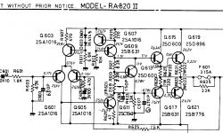
    For information, in the Rotel RA-820, the terminal transistors are a pair of 2SD896 / 2SB776. I propose to compare them with the BDs used here.
    Copy amplifier Rotel RA-820

    I repeat the question to the author's colleague. What are your impressions of using the BT - XS3868 module?
  • #18
    Ibuprom
    Level 26  
    I would be more inclined to the opinion that it is difficult to find the original BD911 / BD912 now. As these are general purpose transistors, various "garbage" can be labeled as long as the housing is correct. After all, the original amplifier worked for many years on this pair and these transistors were hardly spared in this amplifier.
  • #19
    tytka
    Level 21  
    Yes, the current BD911 / BD912 is completely different than it used to be.
    But despite everything, I remember from my experience from years ago that the amplifier with them was not very musical, and switching to another one (suggested for audio) resulted in an improvement in the sound.

    Anyway, I "admire" people who set about making copies of something good, but do not bother to assemble components worthy of it (similar to those in the original).
  • #20
    rosomak19
    Level 22  
    Exactly, once I repaired a Unitra amplifier, I ordered these BDs, replaced the controls, everything was fine, I turned it on, even checked it, but as soon as I increased the volume a little - buuummm. Then I exchanged for other transistors and it was quiet. But where I am going, at the urging of a friend from this forum, I broke the transistor I bought and the old original one. What appeared to my eyes, laughter in the room, now I knew why, after slightly turning the volume knob, they burned out. The difference in the size of the transistor structure was huge!
  • #21
    conisl
    Level 11  
    tytka wrote:
    conisl wrote:
    There may be something wrong with the diagram.

    A friend deigns to joke?
    There is no need to stick to the Rotel tip diagram, which was the standard, because it is a proven design. Well, unless my colleague, the author redrawn the diagram incorrectly, or made some corrections.

    That's what I meant. I do not believe that the author of this project used exactly the transistors as in the diagram. Maybe some replacement had different parameters, maybe some error and misfortune (in this case, burned transistors) ready. I used to deal with transistor power amplifiers as a hobby and never burned transistors.

    best regards
  • #22
    Owen27
    Level 11  
    tytka wrote:
    I repeat the question to the author's colleague. What are your impressions of using the BT - XS3868 module?

    Similar, it hums when it should be quiet and sometimes digital noise is heard.

    Out of curiosity, I will replace the transistors one day, TIP35 / 36 should be ok.
  • #23
    Ibuprom
    Level 26  
    Why don't you give the transistors intended for this? For example, 2SA1943 / 2SC5200 - for all ... PLN 11 per pair. Although I use chutes from old devices to be sure of their originality, the new ones should not be terribly low-quality.
  • #24
    MUGOL 2
    Level 13  
    To colleague Owen27:
    Did the colleague check with the oscilloscope if there are unwanted oscillations at the output (without the connected signal at the input)?
    Did the colleague design the power amplifier printing himself?
    Taking a quick look at the print, there is one serious mistake. The signal ground (elements R604, C604 and C606) is connected to the ground of the power path. Taking into account the fact that there is no RC (low-pass filter) output at the output, the amplifier will sometimes behave like a generator from time to time.
    I propose to create a separate ground for these three elements and connect with a separate wire (as thick as possible) to the ground as close to the capacitors C905 and C906 as possible.

    You can also do it differently - the mass of the R604, C604 and C606 elements can be connected with the mass of the color regulator module, while the mass with the other elements in the terminal (R612, R614, R624, C608, C615, C616) as separate and connected with a possibly thick cable between the C905 And C906.
  • #25
    tytka
    Level 21  
    Buddy MUGOL 2, the author seems to have made the tiles according to the description from the link provided by him, so he is not the direct culprit of connecting these masses. And it seems his experience is too little to grasp it.

    I think that you could possibly try to make a signal ground point, connect R604, C604, C606 to it, and the ground of the preamplifier. And then connect this point to the power ground through a 10 ? resistor.

    Owen27 wrote:
    Similar, it hums when it should be quiet and sometimes digital noise is heard

    Which confirms my experience. Once I bought such a module just to see what it is worth, unfortunately I quickly threw it into the corner. I was surprised when I saw something like that in your design.
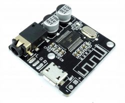
    I propose to replace it with, for example:
    Copy amplifier Rotel RA-820

    Owen27 wrote:
    Out of curiosity, I will replace the transistors one day, TIP35 / 36 should be ok.

    Why did you make the board for TO220 transistors? This limits the room for maneuver, because most good transistors are offered in housings with a larger lead spacing - TO3P, TO247.
  • #26
    padus
    Level 11  
    Will the author praise how he mounted the buttons for this housing?
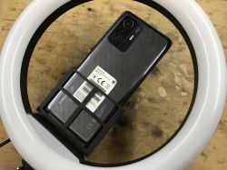
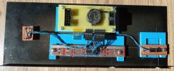
    Copy amplifier Rotel RA-820
    You can't see anything from the front, i.e. the screws don't pass through. Is the electronics mount on screws to the blue printed plastics that are stuck to the sheet metal? If so, what glue? Well, unless some soldering.
    I would appreciate some tips as DIY faceplates are always a difficult matter.
  • #27
    Ibuprom
    Level 26  
    Owen27 wrote:
    tytka wrote:
    I repeat the question to the author's colleague. What are your impressions of using the BT - XS3868 module?

    Similar, it hums when it should be quiet and sometimes digital noise is heard.

    As it happens with Chinese tiles, everything possible was saved there. Behind Link it follows that you need to add a small capacitor and the noise disappears. Of course, nothing stands in the way of improving the factory with other capacitors. And it should be quiet. It's just hard to believe that chipsets with such flaws were released on the market - it had to be an obvious design problem.
  • #28
    Owen27
    Level 11  
    Thank you for your comments, if I find time, I will test it.
    pawel_aa who designed the board, claims that the amplifier can work on TO220, I changed the board a bit so as not to bend the legs of the transistors, changing to TO247 will be a problem.
    padus wrote:
    Is the electronics mount on screws to the blue printed plastics that are stuck to the sheet metal? If so, what glue?

    Exactly, stuck with a droplet.
  • #29
    padus
    Level 11  
    Quote:
    Exactly, stuck with a droplet.

    Thanks.
  • #30
    tytka
    Level 21  
    Ibuprom wrote:
    Behind Link it follows that a small capacitor needs to be added and the noise disappears.

    I found my module and checked it. Unfortunately, it helps as much as incense for a dead man (and I've tested with other capacities as well). This module is a failure.

    Owen27 wrote:
    pawel_aa, who designed the board, claims that the amplifier can work on TO220, I changed the board a bit so as not to bend the legs of the transistors, when switching to TO247 it will be a problem.

    Just because it "can work" doesn't mean it's the best option. You had to make a PCB for both spacings, you would have a universal one and it would be easy to change the transistors.