logo elektroda
logo elektroda
X
logo elektroda

Flashing LED Signal Lamp 838: Enhance Brightness with 230V LED Bulbs, Panels & Strips

zyznos321 5583 10
ADVERTISEMENT
Treść została przetłumaczona polish » english Zobacz oryginalną wersję tematu
  • #1 16614447
    zyznos321
    Level 10  
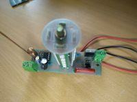
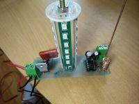
    I recently bought a led signal lamp for the gate on the Allegro, given in the subject. The lamp flashes in such a way that it goes out for a moment, and then it flashes for another moment like a strobe and so on. It is powered by 230v. Unfortunately, I am not satisfied with the amount of light that comes out of it. During the day and in the evening it is barely visible.

    I have a lot of 230v led bulbs and LED panels and strips for lower voltages. Someone can know if it is easy to change this system to make the lamp shine stronger.

    Thank you in advance for your help :)
    Flashing LED Signal Lamp 838: Enhance Brightness with 230V LED Bulbs, Panels & Strips Flashing LED Signal Lamp 838: Enhance Brightness with 230V LED Bulbs, Panels & Strips Flashing LED Signal Lamp 838: Enhance Brightness with 230V LED Bulbs, Panels & Strips Flashing LED Signal Lamp 838: Enhance Brightness with 230V LED Bulbs, Panels & Strips
    Flashing LED Signal Lamp 838: Enhance Brightness with 230V LED Bulbs, Panels & Strips Flashing LED Signal Lamp 838: Enhance Brightness with 230V LED Bulbs, Panels & Strips


    Update:
    I checked it quickly and the output for the diodes is a little over 5v (for each of the 4 strips).
    Is it possible to replace any resistor or other element and easily make it so that the output is 12 or 230v in order to mount other LEDs?
  • ADVERTISEMENT
  • Helpful post
    #2 16614511
    goldi74
    Level 43  
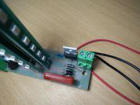
    The LED current is set by the 180? resistors (181 marking) at the bottom of each LED strip. You can try to reduce their value, but you have to take into account a possible reduction in lamp life.
  • ADVERTISEMENT
  • #3 16614520
    zyznos321
    Level 10  
    goldi74 wrote:
    The LED current is set by the 180? resistors (181 marking) at the bottom of each LED strip. You can try to reduce their value, but you have to take into account a possible reduction in lamp life.


    It seems to me that it would be better to increase the current or voltage at the output of the circuit and completely change the LED strips to other ones, so as not to worry that they may turn off at any moment. Can it be done easily?
  • Helpful post
    #4 16615278
    kotbury
    Gantry automation specialist
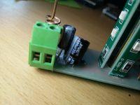
    You can add your narrower ones in the gaps between the original strips, supplemented with lossy resistors, but first check the supply voltage (e.g. on the legs of a large capacitor).
    Connecting the strips themselves to the existing LED poles is risky - there is some complicated connection of LEDs in series - parallel and the resistor is not too strong ...
    And be careful - depending on the polarity of the neutral and the phase, the full mains voltage may appear on the system.
  • ADVERTISEMENT
  • Helpful post
    #5 16615300
    HD-VIDEO
    Level 43  
    There is a limited current there, because there is a transformerless power supply, and the value of the serial capacitor of this power supply limits the current also for LEDs.

    And this capacitor should also be replaced with a better quality one
  • #6 16615676
    andrzej lukaszewicz
    Level 41  
    It is a typical lamp interrupter modeled on lucy nice or kiaro came. Instead of this LED miracle solder / mount the socket on the E14 thread and give a normal 25W bulb can be milky.
    I use a lot of automation and led lamps, I avoid it like a fire, because you can't see the carcass, the master is a beninca lamp with one led, visible only at night, and producers boast about energy-saving solutions with lamps as above or the ability to turn off the LCD display or LEDs on disc that download mW. :idea: Meanwhile, crap-quality transformers made by the Yellow River heat up to 100 degrees Celsius and eat several dozen W during idle operation.
  • ADVERTISEMENT
  • #7 16615732
    zyznos321
    Level 10  
    It seems to me that soldering the lamp holder alone will not do anything, because the LEDs in this lamp are powered by 5-6v. An ordinary 230v bulb will not shine as it should: /
  • Helpful post
    #8 16615903
    andrzej lukaszewicz
    Level 41  
    If it is a 230V lamp, it is interrupted by a triac. So if you remove the led + series resistor + rectifier diodes (or whatever is there) it must work. You just need to know what you're doing.
    Here is the ancestor of this lamp:
    https://www.elektroda.pl/rtvforum/topic1943841.html
    https://www.elektroda.pl/rtvforum/topic3224080.html
  • #9 16615919
    zyznos321
    Level 10  
    Ok, thx. Unfortunately, I do not fully understand what it is responsible for in this system, and I do not want to burn anything: /
  • Helpful post
    #10 16615955
    kotbury
    Gantry automation specialist
    Quote:
    If it is a 230V lamp, it is interrupted by a triac

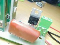
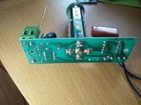
    No, not a triac. In this lamp, the flashing is controlled by the high-voltage Darlington ST901T transistor (photo), which is already located after the rectifier and there will be no specific modification of the board (replacing it with a triac inserted in front of the rectifier, and the rectifier itself must be converted to a two-diode one-wave bulb), it controlled a 220V mains bulb . (see the topic https://www.elektroda.pl/rtvforum/topic2532311.html at the end of the first post).
    You probably won't put a low-voltage bulb (let's say 6V) into the current system because its current efficiency is up to 100 mA. In fact, for the same reason you won't put in more powerful LEDs because this "power supply" will not do.
    So to improve the light or to use a 220V bulb (ordinary or LED), converting the control to a triac, leaving the existing system only to power the blinker or completely change the middle - e.g. the above-mentioned Nice Lucy 220V - the PCB even seems similar.
    And leaving aside the electrical discussions - we're about inserting light bulbs, and is this screw sticking out at the top not holding something? Because if it is needed for something, after converting it into a light bulb, you need to buy a holder for it.
    PS - does your control panel have no additional 24V signaling output? (most drivers have) - then without combining you connect a 24V bulb without any interrupter.
  • #11 16616870
    zyznos321
    Level 10  
    Thanks for explaining everything. The screw is not needed for anything. The lamp is powered from the same output as the engine and it is convenient for me, because the driver can sometimes spin (e.g. when struck by lightning) and then the engine works (most likely to the right and left at the same time, because it stands still and makes a sound) . Thanks to the lamp connected to the same output, I can see that something is wrong and run to disconnect the electricity :)

    Most likely I will make the circuit breaker according to the instructions from the topic you provided. It will definitely be cheaper than buying a second lamp. By the way, I will learn to etch PCBs.

    Thanks again to everyone for your help :)

Topic summary

The discussion revolves around enhancing the brightness of a 230V LED signal lamp, specifically model 838, which the user finds insufficiently visible both during the day and at night. Suggestions include modifying the LED current by adjusting resistors, replacing the existing LED strips with higher quality ones, or using a standard E14 socket for a conventional bulb. Concerns about the lamp's power supply, which is transformerless and limits current, are raised, along with the risks of incorrect modifications. Users discuss the feasibility of using a triac for better control and the potential for DIY circuit modifications to improve performance. The user expresses intent to learn PCB etching for future enhancements.
Summary generated by the language model.
ADVERTISEMENT