logo elektroda
logo elektroda
X
logo elektroda

2.5 kW Induction Heater ZVS Circuit with IRFP260, Full Bridge IRFP460, and TC4421/TC4422

bzyk69ak47 20100 13
ADVERTISEMENT
Treść została przetłumaczona polish » english Zobacz oryginalną wersję tematu
  • #1 16954284
    bzyk69ak47
    Level 13  
    Hello everyone :D
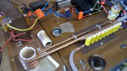
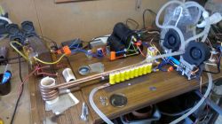
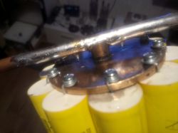
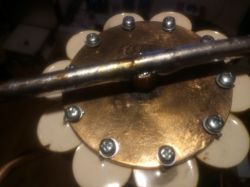
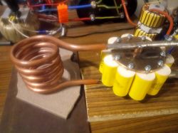
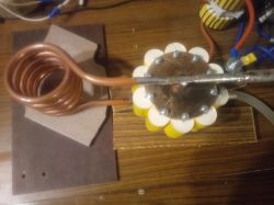
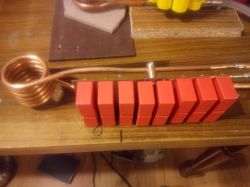
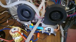
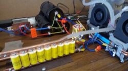
    Let me start with the fact that I recently started playing with induction heating, I made the heater on the generally circulating diagram of the ZVS heater, but on 2 IRFP260 transistors there is no craze, with 26V power supply I get almost 40A, it is enough to heat the M12 screw / 100 to almost 600C, here are some photos of the construction ... 2.5 kW Induction Heater ZVS Circuit with IRFP260, Full Bridge IRFP460, and TC4421/TC4422 2.5 kW Induction Heater ZVS Circuit with IRFP260, Full Bridge IRFP460, and TC4421/TC4422 2.5 kW Induction Heater ZVS Circuit with IRFP260, Full Bridge IRFP460, and TC4421/TC4422 2.5 kW Induction Heater ZVS Circuit with IRFP260, Full Bridge IRFP460, and TC4421/TC4422
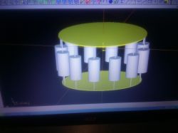
    but I came across a simple layout with reportedly 2.5kW power on a full bridge with IRFP460, unfortunately without a description, I would like to ask your honorable colleagues whether it is worth building this system, is it correct, and any suggestions whether I can use TC4421 / TC4422 as drivers because I have these, and how many turns GDT do and on what core. 2.5 kW Induction Heater ZVS Circuit with IRFP260, Full Bridge IRFP460, and TC4421/TC4422
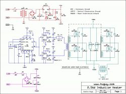
    Many thanks in advance for your interest and any hints ... :D
    Best regards.

    Added after 7 [minutes]:

    Of course, power supply without a doubler, a bridge and 2x12000uF / 250V filtration in series which will give 6000uF 500V, a bit low, but at the moment I have only 3 pcs of such capacitors, I have 2 pcs 2200uF / 450V so I can add them in parallel to it was 10400uF ...
  • ADVERTISEMENT
  • #2 16954452
    keseszel
    Level 26  
    Dude, before you start writing such DY think about what you want to write. I understand that you did something and want to show off, but you present a typical "toilet" that is under construction.
    My DY would be - wire antenna removal, 4kw wire meter. and beware - works great.
    Nice design, description MASAKRA.
  • ADVERTISEMENT
  • #3 16956005
    jarek_lnx
    Level 43  
    I wonder how the inductance of the coil is related to the inductance of this large loop that you made between the coil and the capacitors, the more field you create outside the coil, the less active power you can get.
  • ADVERTISEMENT
  • #4 16956092
    bzyk69ak47
    Level 13  
    Hello, as for the first answer, I will add thanks for the criticism, but whatever the criticism makes sense if it is at least a little constructive ....
    And when it comes to this loop, I did it for a reason, here http://inductionheatertutorial.com/ link to a rather extensive article in which it is probably explained on page 3 ...
  • #5 16956212
    jarek_lnx
    Level 43  
    But these are two independent matters, the equalization of the capacitors current requires connection from the other side, but the large distance of the capacitors from the coil and the large area of the loop outside the coil is your individual work, note that in factory inductors the wires outside the active part are very close to each other, which reduces their inductance. Anyway, the coil itself is also tightly fitted to the heated object, so that as much of the apparent power as possible can be turned into active power.
  • #6 16957563
    bzyk69ak47
    Level 13  
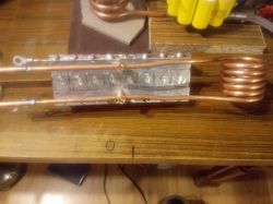
    Hello again, thanks for the hint, this is an important message ... I have never seen the original heater from the inside, always like the original in the housing ... But by connecting the capacitors in parallel on the Cu rails it is impossible not to make a loop, and if I connected them in this way... 2.5 kW Induction Heater ZVS Circuit with IRFP260, Full Bridge IRFP460, and TC4421/TC4422


    and he just connected the coil of the inductor to the copper linings ....
  • #7 16957884
    jarek_lnx
    Level 43  
    Quote:
    Hello again, thanks for the hint, this is an important message ... I have never seen the original heater from the inside, always like the original in the housing ...
    And I can't say that I saw, I wrote about inductors. I rely on my experience in systems with small inductances and the known fact that each loop has inductance, and additional inductance outside the inductor limits the maximum current in the circuit, the resistance of long wires-tubes is also not beneficial. And if we can not reduce the length of the wire, then you need to reduce the area of the loop by bringing the wires closer together.

    Quote:
    Cu can't be without loops, and if I connected them in this way ...
    This is an idea, the tubes should be led through the center so that they go close together and connect in the middle of each shield.
  • #8 16957953
    bzyk69ak47
    Level 13  
    Great, and thus referring to the topic, does the diagram on the full bridge seem correct and meaningful? The biggest disadvantage of the ZVS system is that it needs a low supply voltage and a lot of current to obtain the same power as with a few or a dozen or more amps when powered from the mains, and thus a large, heavy transformer that wants to be eliminated from the system ...
    And IRFP460 are cheap ... and generally all components for this "2.5kW" system I would have on hand, the question of what GDT and separation transformer circuit to give ...
  • ADVERTISEMENT
  • #9 16958638
    jarek_lnx
    Level 43  
    There is no pull-down resistor on the TL494 output, I would give 1k.
  • #10 16961319
    bzyk69ak47
    Level 13  
    i.e. a resistor plugged in between the connected pins 9 and 10 and the mass, right?
  • #12 16969057
    bzyk69ak47
    Level 13  
    welcome back :D over the last days I tested 2 configurations of the inductor, power supply and capacitors connection, and I noticed that they were evenly and least warmed (capacitors) in this very first circuit with a large loop, as for currents, these are idle, when the inductor is empty, from 16A at the beginning to 10 and 8A in turn with connections successively on copper shields and on the board, what puzzles me is the last two, especially where capacitors are on shields that were connected to the power supply not through the entire axis but only on the same in the middle, so the path to each of the capacitors of the same length is still more noticeably warming up from the inductor side. 2.5 kW Induction Heater ZVS Circuit with IRFP260, Full Bridge IRFP460, and TC4421/TC4422 2.5 kW Induction Heater ZVS Circuit with IRFP260, Full Bridge IRFP460, and TC4421/TC4422 2.5 kW Induction Heater ZVS Circuit with IRFP260, Full Bridge IRFP460, and TC4421/TC4422 2.5 kW Induction Heater ZVS Circuit with IRFP260, Full Bridge IRFP460, and TC4421/TC4422 2.5 kW Induction Heater ZVS Circuit with IRFP260, Full Bridge IRFP460, and TC4421/TC4422 2.5 kW Induction Heater ZVS Circuit with IRFP260, Full Bridge IRFP460, and TC4421/TC4422
  • #13 16970060
    jarek_lnx
    Level 43  
    Idle current dropped, so goodness improved, did you check how the metal heats?
  • #14 16973797
    bzyk69ak47
    Level 13  
    Hello, yes, I checked it, it warms up a little better, but it's by the eye, judging by the color of the charge, I didn't connect the thermometer ... I wanted to make a smaller inductor, such as a horseshoe-shaped one, for heating screws in portable versions, but it turned out 4 turns is not enough and the transistors flew after inserting the charge. Now I decided to give 2 IRFP260 in parallel, I just need to convert the heat sinks. For now, the system on the full bridge with IRFP460 goes off because I hunt for ferrite cores toroids for the transformer powering the inductor, for GDT I will give ferrite fi 25 with 3E25, in SSTC it works and it should work here, I also have a full bridge with IRFP460.

Topic summary

The discussion revolves around the construction and optimization of a 2.5 kW induction heater using a ZVS circuit with components such as IRFP260 and IRFP460 transistors, along with TC4421/TC4422 drivers. The original poster shares their experience with a ZVS heater that successfully heats an M12 screw to nearly 600°C using a 26V power supply. They seek advice on the feasibility of building a full bridge circuit with IRFP460 and inquire about the appropriate number of turns for the gate drive transformer (GDT) and the configuration of capacitors. Responses highlight the importance of minimizing inductance in the circuit, the relationship between coil design and power efficiency, and suggestions for improving the layout to enhance performance. The poster also experiments with different configurations and notes improvements in heating efficiency.
Summary generated by the language model.
ADVERTISEMENT