logo elektroda
logo elektroda
X
logo elektroda

Automating Traditional Wired Roller Shutters with Arduino and Domoticz on Raspberry Pi 3

klakier_2006 4794 13
ADVERTISEMENT
Treść została przetłumaczona polish » english Zobacz oryginalną wersję tematu
  • #1 16965366
    klakier_2006
    Level 9  
    Hello. I have domoticz installed on a raspberry pi 3 and I want to use it for simple home automation. I have an arduino uno connected to the raspberry via usb and I use the mysensors library. The problem concerns the control of window blinds. I want to control traditional wired roller shutters with relays controlled by arduino and, additionally, with the possibility of opening and closing the roller shutters with buttons. For each roller blind I designate two releys in arduino - one roller blind up, the other roller blind down. Each relay is assigned its own button in the on / off type. However, this solution is defective because it is possible to switch on the relay responsible for raising and lowering the roller shutter at the same time. The question is how to make the switching of one relay automatically give information to the arduino about the need to turn off the long relay.
    Do you have a problem with Arduino? Ask question. Visit our forum Arduino.
  • ADVERTISEMENT
  • #2 16965390
    czareqpl
    Level 33  
    klakier_2006 wrote:
    The question is how to make the switching of one relay automatically give information to the arduino about the need to turn off the long relay.


    It is enough to add in the code the command to turn off both relays before the procedure of turning on one of them is carried out ...
  • #3 16965435
    k9mil
    Level 16  
    klakier_2006 wrote:
    However, this solution is defective because it is possible to simultaneously turn on the relay responsible for raising and lowering the roller shutter

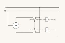
    Wire the relays according to this diagram and you will be physically protected from being energized for closing and opening at once.
    Automating Traditional Wired Roller Shutters with Arduino and Domoticz on Raspberry Pi 3
  • #4 16965541
    Darek0026
    Level 31  
    k9mil wrote:
    klakier_2006 wrote:
    However, this solution is defective because it is possible to simultaneously turn on the relay responsible for raising and lowering the roller shutter

    Wire the relays according to this diagram and you will be physically protected from being energized for closing and opening at once.
    Automating Traditional Wired Roller Shutters with Arduino and Domoticz on Raspberry Pi 3


    This diagram is correct, but in practice three relays are used to control the motor. The third disconnects "N" from the motors for safety.
  • ADVERTISEMENT
  • #5 16966529
    klakier_2006
    Level 9  
    Thanks for your interest in my problem, but can you tell me what the command to turn off the relays should sound like and where to enter it? I must admit that I am a total novice when it comes to arduino. As an attachment I am adding a file with my sketch. It is written for controlling two blinds.


    [syntax=csharp]
    // Enable debug prints to serial monitor
    #define MY_DEBUG


    // Enable and select radio type attached
    //#define MY_RADIO_NRF24
    //#define MY_RADIO_RFM69

    // Set LOW transmit power level as default, if you have an amplified NRF-module and
    // power your radio separately with a good regulator you can turn up PA level.
    //#define MY_RF24_PA_LEVEL RF24_PA_LOW

    // Enable serial gateway
    #define MY_GATEWAY_SERIAL

    // Define a lower baud rate for Arduino's running on 8 MHz (Arduino Pro Mini 3.3V & SenseBender)
    #if F_CPU == 8000000L
    #define MY_BAUD_RATE 38400
    #endif

    // Flash leds on rx/tx/err
    // #define MY_LEDS_BLINKING_FEATURE
    // Set blinking period
    // #define MY_DEFAULT_LED_BLINK_PERIOD 300

    // Inverses the behavior of leds
    // #define MY_WITH_LEDS_BLINKING_INVERSE

    // Enable inclusion mode
    #define MY_INCLUSION_MODE_FEATURE
    // Enable Inclusion mode button on gateway
    #define MY_INCLUSION_BUTTON_FEATURE

    // Inverses behavior of inclusion button (if using external pullup)
    //#define MY_INCLUSION_BUTTON_EXTERNAL_PULLUP

    // Set inclusion mode duration (in seconds)
    #define MY_INCLUSION_MODE_DURATION 60
    // Digital pin used for inclusion mode button
    #define MY_INCLUSION_MODE_BUTTON_PIN 3

    // Uncomment to override default HW configurations
    //#define MY_DEFAULT_ERR_LED_PIN 4 // Error led pin
    //#define MY_DEFAULT_RX_LED_PIN 6 // Receive led pin
    //#define MY_DEFAULT_TX_LED_PIN 5 // the PCB, on board LED

    #include
    #include
    #include

    // Enable repeater functionality for this node
    #define MY_REPEATER_FEATURE


    #define RELAY_1 4 // Arduino Digital I/O pin number for first relay (second on pin+1 etc)
    #define RELAY_2 5
    #define RELAY_3 6
    #define RELAY_4 7
    #define NUMBER_OF_RELAYS 4 // Total number of attached relays
    #define RELAY_ON 0 // GPIO value to write to turn on attached relay
    #define RELAY_OFF 1 // GPIO value to write to turn off attached relay

    #define BUTTON_PIN A1
    #define BUTTON2_PIN A2
    #define BUTTON3_PIN A3
    #define BUTTON4_PIN A4


    void before() {
    for (int sensor=1, pin=RELAY_1; sensor
  • ADVERTISEMENT
  • #6 16967467
    k9mil
    Level 16  
    If you connect the relays as shown in the previous diagram, it will be physically impossible to supply power to open and close.

    klakier_2006 wrote:
    Thanks for your interest in my problem, but can you tell me what the command to turn off the relays should sound like and where to enter it? I must admit that I am a total novice when it comes to arduino. As an attachment I am adding a file with my sketch. It is written for controlling two blinds.

    For example, yes, if the appropriate RELAY1 and RELAY2 as well as RELAY3 and RELAY4 are responsible for controlling the shutters.
    [syntax=c]
    // Enable debug prints to serial monitor
    #define MY_DEBUG


    // Enable and select radio type attached
    //#define MY_RADIO_NRF24
    //#define MY_RADIO_RFM69

    // Set LOW transmit power level as default, if you have an amplified NRF-module and
    // power your radio separately with a good regulator you can turn up PA level.
    //#define MY_RF24_PA_LEVEL RF24_PA_LOW

    // Enable serial gateway
    #define MY_GATEWAY_SERIAL

    // Define a lower baud rate for Arduino's running on 8 MHz (Arduino Pro Mini 3.3V & SenseBender)
    #if F_CPU == 8000000L
    #define MY_BAUD_RATE 38400
    #endif

    // Flash leds on rx/tx/err
    // #define MY_LEDS_BLINKING_FEATURE
    // Set blinking period
    // #define MY_DEFAULT_LED_BLINK_PERIOD 300

    // Inverses the behavior of leds
    // #define MY_WITH_LEDS_BLINKING_INVERSE

    // Enable inclusion mode
    #define MY_INCLUSION_MODE_FEATURE
    // Enable Inclusion mode button on gateway
    #define MY_INCLUSION_BUTTON_FEATURE

    // Inverses behavior of inclusion button (if using external pullup)
    //#define MY_INCLUSION_BUTTON_EXTERNAL_PULLUP

    // Set inclusion mode duration (in seconds)
    #define MY_INCLUSION_MODE_DURATION 60
    // Digital pin used for inclusion mode button
    #define MY_INCLUSION_MODE_BUTTON_PIN 3

    // Uncomment to override default HW configurations
    //#define MY_DEFAULT_ERR_LED_PIN 4 // Error led pin
    //#define MY_DEFAULT_RX_LED_PIN 6 // Receive led pin
    //#define MY_DEFAULT_TX_LED_PIN 5 // the PCB, on board LED

    #include
    #include
    #include

    // Enable repeater functionality for this node
    #define MY_REPEATER_FEATURE


    #define RELAY_1 4 // Arduino Digital I/O pin number for first relay (second on pin+1 etc)
    #define RELAY_2 5
    #define RELAY_3 6
    #define RELAY_4 7
    #define NUMBER_OF_RELAYS 4 // Total number of attached relays
    #define RELAY_ON 0 // GPIO value to write to turn on attached relay
    #define RELAY_OFF 1 // GPIO value to write to turn off attached relay

    #define BUTTON_PIN A1
    #define BUTTON2_PIN A2
    #define BUTTON3_PIN A3
    #define BUTTON4_PIN A4


    void before() {
    for (int sensor=1, pin=RELAY_1; sensor
  • #7 16969796
    klakier_2006
    Level 9  
    The diagram protects me against giving simultaneous voltage in two directions, but I would prefer to solve this issue in software because everything is to be controlled domoticz on rastberry pi and if I connect it according to the diagram, the effect is when two relays are turned on, the blind goes in one direction when turned off both are in the other direction, if one is on and the other is on, it stands. This is a partial success because on the domoticz panel it is impossible to describe which switch is responsible for raising and which for lowering the roller blind, which causes a haos, the more so because, to be honest, it is just a model. Ultimately, the blinds are to be 12 pcs. I would also like to assign one of the "A" buttons on the arduino in such a way that it lowers all the blinds and raises them all. Do you think such a thing can be done?
  • Helpful post
    #8 16969978
    es2
    Level 16  
    klakier_2006 wrote:
    The diagram prevents me from applying voltage to two directions at the same time, but I would prefer to solve this issue in software

    Create a function e.g.
    Code: C / C++
    Log in, to see the code

    Call it where necessary with the appropriate parameter and you have software protection. naturally, instead of dir == 1 define constants with direction e.g.
    Code: C / C++
    Log in, to see the code


    klakier_2006 wrote:

    because everything is to be controlled by domoticz on the rastberry pi and if I connect it according to the diagram, the effect is when two relays are turned on, the blind goes in one direction, when both are turned off, then in the other direction, if one is turned on and the other is turned on, it stands.

    You have something wrongly connected because the diagram shows something else.
  • #9 16978714
    klakier_2006
    Level 9  
    I checked everything again and I actually connected it wrong. Everything worked. Thanks.
  • ADVERTISEMENT
  • #10 17506028
    mchrzan
    Level 6  
    Hello
    And how does this solution work for you?
    I also wanted to cover the whole thing with wires so that I do not have 12 wifi over my head
    can you write how you got it covered?
    how many cables go from the roller shutters to the control panel etc?
    it looks like this for me
    a 4-core cable goes from the shutter to the box, and from the box, a 5-core cable goes to one box
    how to get it, can you help?
  • #11 17561840
    boe6666
    Level 8  
    If I can add anything. I have an identical installation at home. Classic roller shutters, controlled by a manual roller shutter switch (mechanical protection against short circuit of both at once). I used 2 relays to control the roller shutters, but I made the connection of the working contacts in such a way that if any relay is on, it cuts off the phase going to the roller shutter switch. The effect is that when the roller shutter works with domotica, the wall switches do not work physically. (the diagram is simple - analyze it carefully - it can be connected like this). As for the control itself - it is enough to precede the function that activates a given contactor - as it has already been written - switching off the second contactor (LO state) paired with the first. I wrote this operation in arduino (once atmega, now stm32) and no matter how I control it from the domoticz level - there will never be a short circuit of both contactors.
    I hope I helped with something. Regards.
  • #12 17567179
    omnixcrs
    Level 11  
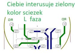
    I think that there is no use in programming, the program can always go stupid or hang and then you lie down. Protection against giving two phases at once is performed on the contacts of relays. To control the roller shutter, two relays with SPDT contacts are used, i.e. one make and one break. Look at a piece of my schematic how to connect it:
    Automating Traditional Wired Roller Shutters with Arduino and Domoticz on Raspberry Pi 3

    of course, RG and RD in the drawing are the up and down phase for the roller shutter
  • #13 17567701
    boe6666
    Level 8  
    You are right, now I remembered that the connection I wrote about earlier also excludes giving both phases at once from both contactors :) This is somewhat logical, but I did not mention it. As for the changes to arduino - you are right that the program may hang, but it's better to add this exclusion. From practice - for 2 years I have been using various hardware combinations and the program has never crashed - but it can always happen.

    One more thing, if it is possible - I have not yet solved the problem with the state of opening the blinds and, if necessary, protection against blocking the curtain - I have ordinary motors without encoders and without overloads. I considered a multi-turn potentiometer + spring link mechanism, but it's quite complicated.

    Perhaps the best would be a rotary pulser + a circle at the very top of the armor. The point is that when unfolding the blind - in the event of blocking the armor - the armor and cartridge may be completely destroyed ... Someone may have solved it. ???
  • #14 18611375
    marpac09
    Level 1  
    witam czy jest mi w stanie ktos pomoc w powieleniu tego skechu na dwie rolety. juz nic mi do głowy nie przychodzi.// Enable debug prints to serial monitor

    Dodano po 41 [sekundy]:

    // Enable debug prints to serial monitor
    #define MY_DEBUG

    #define MY_GATEWAY_SERIAL

    // Enable and select radio type attached
    //#define MY_RADIO_NRF24

    //#define MY_RF24_PA_LEVEL RF24_PA_LOW

    //#define MY_REPEATER_FEATURE

    // uncomment if we want to manually assign an ID/////////////////////////////////////////////////////////////
    //#define MY_NODE_ID 1
    // Define a lower baud rate for Arduino's running on 8 MHz (Arduino Pro Mini 3.3V & SenseBender)
    //#if F_CPU == 8000000L
    //#define MY_BAUD_RATE 38400
    //#endif

    // Flash leds on rx/tx/err
    // #define MY_LEDS_BLINKING_FEATURE
    // Set blinking period
    // #define MY_DEFAULT_LED_BLINK_PERIOD 300

    // Inverses the behavior of leds
    // #define MY_WITH_LEDS_BLINKING_INVERSE

    // Enable inclusion mode
    #define MY_INCLUSION_MODE_FEATURE
    // Enable Inclusion mode button on gateway
    #define MY_INCLUSION_BUTTON_FEATURE

    // Inverses behavior of inclusion button (if using external pullup)
    //#define MY_INCLUSION_BUTTON_EXTERNAL_PULLUP

    // Set inclusion mode duration (in seconds)
    #define MY_INCLUSION_MODE_DURATION 60
    // Digital pin used for inclusion mode button
    #define MY_INCLUSION_MODE_BUTTON_PIN 3

    // Uncomment to override default HW configurations
    //#define MY_DEFAULT_ERR_LED_PIN 4 // Error led pin
    //#define MY_DEFAULT_RX_LED_PIN 6 // Receive led pin
    //#define MY_DEFAULT_TX_LED_PIN 5 // the PCB, on board LED

    #include
    #include
    #include

    #define BUTTON_UP 54// Arduino Digital I/O pin number for up button
    #define BUTTON_DOWN 55 // Arduino Digital I/O pin number for down button
    //#define BUTTON_STOP_PIN 5 // Arduino Digital I/O pin number for stop button
    //#define RELAY_DIR_PIN 6 // Arduino Digital I/O pin number for direction relay
    //#define RELAY_POWER_PIN 7 // Arduino Digital I/O pin number for power relay
    #define RELAY_UP 22
    #define RELAY_DOWN 23
    #define NUMBER_OF_RELAYS 2
    #define RELAY_ON 1
    #define RELAY_OFF 0
    //#define RELAY_DOWN 1
    //#define RELAY_UP 0
    #define DIRECTION_DOWN 0
    #define DIRECTION_UP 1
    #define SKETCH_NAME "Cover by Marek"
    #define SKETCH_VER "1.0"
    #define CHILD_ID_COVER 0 // sensor Id of the sensor child
    #define STATE_UP 100 // 100 is open - up
    #define STATE_DOWN 0 // 0 is closed - down
    //#define CHILD_ID_CALIBRATE 1 // sensor Id of the sensor child to calibrate
    #define CHILD_ID_SET 1 // sensor Id of the sensor child to init the roll time
    #define PRESENT_MESSAGE "Cover sensor for hass"
    const int LEVELS = 100; //the number of levels
    float rollTime = 10.0; //the overall rolling time of the shutter
    const bool IS_ACK = false; //is to acknowlage
    static bool initial_state_sent = false;//for hass we need at list one state send at begining

    // debouncing parameters
    int value = 0;
    int oldValueUp = 0;
    int oldValueDown = 0;
    int oldValueStop = 0;
    //static unsigned long last_interrupt_time_up = 0;
    //static unsigned long last_interrupt_time_down = 0;
    //static unsigned long debounce_time = 200;

    Bounce debouncerUp = Bounce();
    Bounce debouncerDown = Bounce();
    Bounce debouncerStop = Bounce();

    // shutter position parameters
    float timeOneLevel = rollTime / LEVELS;
    int requestedShutterLevel = 0;
    int currentShutterLevel = 0;
    unsigned long lastLevelTime = 0;
    bool isMoving = false;
    int directionUpDown;

    enum CoverState {
    STOP,
    UP, // Window covering. Up.
    DOWN, // Window covering. Down.
    };

    static int coverState = STOP;

    MyMessage msgUp(CHILD_ID_COVER, V_UP);
    MyMessage msgDown(CHILD_ID_COVER, V_DOWN);
    MyMessage msgStop(CHILD_ID_COVER, V_STOP);
    MyMessage msgPercentage(CHILD_ID_COVER, V_PERCENTAGE);
    //MyMessage msgCode(CHILD_ID_SET, V_IR_SEND);

    void sendState() {
    // Send current state and status to gateway.
    send(msgUp.set(coverState == UP));
    send(msgDown.set(coverState == DOWN));
    send(msgStop.set(coverState == STOP));
    send(msgPercentage.set(currentShutterLevel));
    }

    void shuttersUp(void) {
    #ifdef MY_DEBUG
    Serial.println("Shutters going up");
    #endif
    if (digitalRead(RELAY_DOWN) == RELAY_ON) {
    digitalWrite(RELAY_DOWN, RELAY_OFF);
    wait(50);
    }
    digitalWrite(RELAY_UP, RELAY_ON);

    directionUpDown = DIRECTION_UP;
    isMoving = true;
    coverState = UP;
    sendState();
    }

    void shuttersDown(void) {
    #ifdef MY_DEBUG
    Serial.println("Shutters going down");
    #endif
    if (digitalRead(RELAY_UP) == RELAY_ON) {
    digitalWrite(RELAY_UP, RELAY_OFF);
    wait(50);
    }
    digitalWrite(RELAY_DOWN, RELAY_ON);

    directionUpDown = DIRECTION_DOWN;
    isMoving = true;
    coverState = DOWN;
    sendState();
    }

    void shuttersHalt(void) {
    #ifdef MY_DEBUG
    Serial.println("Shutters halted");
    #endif
    digitalWrite(RELAY_UP, RELAY_OFF);
    digitalWrite(RELAY_DOWN, RELAY_OFF);

    isMoving = false;
    requestedShutterLevel = currentShutterLevel;
    #ifdef MY_DEBUG
    Serial.println("saving state to: ");
    Serial.println(String(currentShutterLevel));
    #endif
    saveState(CHILD_ID_COVER, currentShutterLevel);
    coverState = STOP;
    sendState();
    }

    void changeShuttersLevel(int level) {
    int dir = (level > currentShutterLevel) ? DIRECTION_UP : DIRECTION_DOWN;
    if (isMoving && dir != directionUpDown) {
    shuttersHalt();
    }
    requestedShutterLevel = level;
    }

    void initShutters() {
    #ifdef MY_DEBUG
    Serial.println("Init Cover");
    #endif
    shuttersUp();
    wait((rollTime + timeOneLevel * LEVELS) * 1000);
    currentShutterLevel = STATE_UP;
    requestedShutterLevel = currentShutterLevel;
    }

    void receive(const MyMessage &message) {
    #ifdef MY_DEBUG
    Serial.println("recieved incomming message");
    Serial.println("Recieved message for sensor: ");
    Serial.println(String(message.sensor));
    Serial.println("Recieved message with type: ");
    Serial.println(String(message.type));
    #endif
    if (message.sensor == CHILD_ID_COVER) {
    switch (message.type) {
    case V_UP:
    //Serial.println(", New status: V_UP");
    changeShuttersLevel(STATE_UP);
    //state = UP;
    //sendState();
    break;

    case V_DOWN:
    //Serial.println(", New status: V_DOWN");
    changeShuttersLevel(STATE_DOWN);
    //state = DOWN;
    //sendState();
    break;

    case V_STOP:
    //Serial.println(", New status: V_STOP");
    shuttersHalt();
    //state = IDLE;
    //sendState();
    break;

    case V_PERCENTAGE:
    //Serial.println(", New status: V_PERCENTAGE");
    // if (!initial_state_sent) {
    // #ifdef MY_DEBUG
    // Serial.println("Receiving initial value from controller");
    // #endif
    // initial_state_sent = true;
    // }
    int per = message.getInt();
    if (per > STATE_UP) {
    per = STATE_UP;
    }
    changeShuttersLevel(per);
    //InitShutters(message.getInt());//send value < 0 or > 100 to calibrate
    //sendState();
    break;
    }
    }
    else if (message.sensor == CHILD_ID_SET) {

    if (message.type == V_VAR1) {
    #ifdef MY_DEBUG
    Serial.println(", New status: V_VAR1, with payload: ");
    #endif
    String strRollTime = message.getString();
    rollTime = strRollTime.toFloat();
    #ifdef MY_DEBUG
    Serial.println("rolltime value: ");
    Serial.println(String(rollTime));
    #endif
    saveState(CHILD_ID_SET, rollTime);
    }
    }
    #ifdef MY_DEBUG
    Serial.println("exiting incoming message");
    #endif
    return;
    }

    void before() {

    // Setup the button
    pinMode(BUTTON_UP, INPUT_PULLUP);
    // Activate internal pull-up
    // digitalWrite(BUTTON_UP_PIN, HIGH);
    // attachInterrupt(digitalPinToInterrupt(BUTTON_UP_PIN), upButtonPress, FALLING);

    pinMode(BUTTON_DOWN, INPUT_PULLUP);
    // Activate internal pull-up
    // digitalWrite(BUTTON_DOWN_PIN, HIGH);
    // attachInterrupt(digitalPinToInterrupt(BUTTON_DOWN_PIN), downButtonPress, FALLING);

    // pinMode(BUTTON_STOP_PIN, INPUT_PULLUP);
    // Activate internal pull-up
    // digitalWrite(BUTTON_STOP_PIN, HIGH);

    // After setting up the button, setup debouncer
    debouncerUp.attach(BUTTON_UP);
    debouncerUp.interval(5);
    // After setting up the button, setup debouncer
    debouncerDown.attach(BUTTON_DOWN);
    debouncerDown.interval(5);
    // After setting up the button, setup debouncer
    // debouncerStop.attach(BUTTON_STOP_PIN);
    // debouncerStop.interval(5);

    // Make sure relays are off when starting up
    digitalWrite(RELAY_UP, RELAY_OFF);
    // Then set relay pins in output mode
    pinMode(RELAY_UP, OUTPUT);

    // Make sure relays are off when starting up
    digitalWrite(RELAY_DOWN, RELAY_OFF);
    // Then set relay pins in output mode
    pinMode(RELAY_DOWN, OUTPUT);
    }

    void presentation() {
    // Send the sketch version information to the gateway and Controller
    sendSketchInfo(SKETCH_NAME, SKETCH_VER);
    // Register all sensors to gw (they will be created as child devices)
    present(CHILD_ID_COVER, S_COVER, PRESENT_MESSAGE, IS_ACK);
    // present(CHILD_ID_SET, S_CUSTOM);
    }

    void setup(void) {
    //set up roll time if the saved value is not 255
    #ifdef MY_DEBUG
    Serial.println("getting rolltime from eeprom: ");
    #endif
    float tmpRollTime = loadState(CHILD_ID_SET);
    if (tmpRollTime != 0xff) {
    rollTime = tmpRollTime;
    }
    #ifdef MY_DEBUG
    Serial.println(String(rollTime));
    #endif

    int state = loadState(CHILD_ID_COVER);

    #ifdef MY_DEBUG
    Serial.println("getting state from eeprom: ");
    Serial.println(String(state));
    #endif

    if (state == 0xff) {
    initShutters();
    } else {
    changeShuttersLevel(state);
    }
    }

    void loop(void) {
    if (!initial_state_sent) {
    #ifdef MY_DEBUG
    Serial.println("Sending initial value");
    #endif
    sendState();

    // send(msgCode.set('20.0'));
    // #ifdef MY_DEBUG
    // Serial.println("Requesting initial value from controller");
    // #endif
    // request(CHILD_ID_COVER, V_PERCENTAGE);
    // wait(2000, C_SET, V_PERCENTAGE);
    initial_state_sent = true;
    }

    debouncerUp.update();
    value = debouncerUp.read();
    if (value == 0 && value != oldValueUp) {
    if(isMoving){
    shuttersHalt();
    }
    else{
    changeShuttersLevel(STATE_UP);
    }
    //state = UP;
    //sendState();
    }
    oldValueUp = value;

    debouncerDown.update();
    value = debouncerDown.read();
    if (value == 0 && value != oldValueDown) {
    if(isMoving){
    shuttersHalt();
    }
    else{
    changeShuttersLevel(STATE_DOWN);
    }
    //state = DOWN;
    //sendState();
    }
    oldValueDown = value;

    /* debouncerStop.update();
    value = debouncerStop.read();
    if (value == 0 && value != oldValueStop) {
    shuttersHalt();
    //state = IDLE;
    //sendState();
    }
    oldValueStop = value;
    */

    if (isMoving) {
    unsigned long _now = millis();
    if (_now - lastLevelTime >= timeOneLevel * 1000) {
    if (directionUpDown == DIRECTION_UP) {
    currentShutterLevel += 1;
    } else {
    currentShutterLevel -= 1;
    }
    #ifdef MY_DEBUG
    Serial.println(String(requestedShutterLevel));
    Serial.println(String(currentShutterLevel));
    #endif
    lastLevelTime = millis();
    send(msgPercentage.set(currentShutterLevel));
    }
    if (currentShutterLevel == requestedShutterLevel) {
    shuttersHalt();
    }
    }
    else if (requestedShutterLevel != currentShutterLevel) {
    if (requestedShutterLevel > currentShutterLevel) {
    shuttersUp();
    }
    else {
    shuttersDown();
    }
    lastLevelTime = millis();
    }
    }

Topic summary

The discussion revolves around automating traditional wired roller shutters using an Arduino Uno connected to a Raspberry Pi 3 running Domoticz. The user seeks a solution to prevent simultaneous activation of relays controlling the up and down functions of the shutters. Suggestions include modifying the Arduino code to ensure that activating one relay automatically deactivates the other, thus preventing potential damage. Wiring diagrams are shared to illustrate safe relay connections, and users discuss the importance of both software and hardware protections. The conversation also touches on the possibility of controlling multiple blinds simultaneously and the challenges of integrating manual switches with automated systems.
Summary generated by the language model.
ADVERTISEMENT