logo elektroda
logo elektroda
X
logo elektroda

[Solved] Selecting Low RDS(on) Logic Level N-Mosfet for 3.3V Microcontroller & 12V Motor Control

robiw 9903 29
ADVERTISEMENT
Treść została przetłumaczona polish » english Zobacz oryginalną wersję tematu
  • #1 16992967
    robiw
    Level 26  
    Hello,
    I plan to make a simple PWM system to control a 12V motor controlled from a microcontroller powered by 3.3V, hence the question about a logic level mosfet with the lowest possible RDS(on) resistance, with which I can control a motor with a load current of 10-15A? Will a heatsink be necessary at this current and low RDS(on) resistance? Any example of optoisolation for 3.3V? Thank you in advance...rob
  • ADVERTISEMENT
  • #2 16993027
    diquan
    Level 20  
    As for the mosfet, see PSMN2R7-30PL (100A / 30V / Rds (on) 0.0023 Ohm). The insulation is e.g. Optocoupler 6N137.
  • #3 16993029
    tmf
    VIP Meritorious for electroda.pl
    10-15A is not such a small motor anymore :)
    Use some product selector, e.g. on farnell, after entering N-MOSFET, you select the appropriate tab, then you specify the required parameters and a list of transistors that meet your criteria appears.
    At 10-15A, finding an N-MOSFET with an RDSon small enough to not need a heatsink can be a challenge. With a VGS of around 10V, you can easily get a MOSFET with an RDSon of 8 mOhms, which would give 2W static loss for 15A, so a copper field under the transistor would be enough, and a double-layer board with vias increasing heat conduction would be a good idea.
    Ew. you can think about some H half-bridges - Infineon has excellent ones, e.g.

    Added after 4 [minutes]:

    In the meantime, the colleague above gave the direction to a quite interesting transistor.
  • ADVERTISEMENT
  • #4 16993071
    robiw
    Level 26  
    diquan wrote:
    As for the mosfet, see PSMN2R7-30PL (100A / 30V / Rds (on) 0.0023 Ohm). The insulation is e.g. Optocoupler 6N137.


    23mOhm is a bit much. At 10A, this gives 2.3W of loss :-( . Can you provide an example optoisolation scheme? robin

    Added after 6 [minutes]:

    ....OK, I've already noticed my mistake 2.7mOhm...great, but it's not in TME. I also need a transistor in a TO220 package... robiw
  • #6 16993124
    robiw
    Level 26  
    Of course it's not...but from them I got...free...
    I found:

    INFINEON (IRF) IRLB8748PBF
    Transistor: N-MOSFET; unipolar; logic level; 30V; 92A; 75W
    4.8mOhms

    PLN 2.6...

    I counted the zeros above ;-) . Any proven scheme with an optoisolator? robin
  • #8 16993143
    robiw
    Level 26  
    Even better is the IRL7833PBF...
  • #9 16993173
    tmf
    VIP Meritorious for electroda.pl
    robiw wrote:
    Even better is the IRL7833PBF...


    It's just a small but... if you look at graph 3 (Typical Transfer Characteristics) you'll notice that this transistor has fantastic parameters (like the previous ones) at VGS of 5-6V, and for some 10V. Then you have nominal RDSon. You wrote about control with 3.3V, RDSon will be many times higher. Also, it would be nice to add some minidriver that will increase VGS.
    BTW, why do you need optoisolation? If this is really to work, you would have to completely isolate the power module electrically.
  • #10 16993222
    Anonymous
    Level 1  
  • #11 16993377
    robiw
    Level 26  
    tmf wrote:
    BTW, why do you need optoisolation? If this is really to work, you would have to completely isolate the power module electrically.


    I was just wondering if it makes sense, because the microprocessor system will be powered from the same 12V voltage (through the stabilizer) as the DC motor, but with a different pair of wires ...

    Added after 2 [minutes]:

    Marek_Skalski wrote:
    If you want to provide optoisolation, why not power the gate with a higher voltage, e.g. 12V? You then have a much larger selection of transistors with lower resistance, cheaper, in different packages.


    I will rather give up this isolation, but I will use an additional transistor with pull-up to +12V. Is a typical NPN transistor enough? robin
  • #12 16993436
    krzysiek_krm
    Level 40  
    Hello,
    I think that a good solution is to use a specialized driver: tiny, dirt cheap, easy to drive with almost any logic, available with different output currents, etc.
    robiw wrote:
    because the microprocessor system will be powered from the same 12V voltage (through the stabilizer) as the DC motor, but with a different pair of wires...

    You should probably be a little careful not to inadvertently create a parasitic ground loop, unless that's what you need galvanic isolation for.

    Regards
  • #13 16993483
    yogi009
    Level 43  
    krzysiek_krm wrote:
    I think a good solution is to use a specialized driver


    And that's the essence of this discussion.
  • ADVERTISEMENT
  • #14 16993491
    robiw
    Level 26  
    krzysiek_krm wrote:
    Hello,
    I think a good solution is to use a specialized driver


    Any specific type? I've never used ... robiw
  • #15 16993807
    krzysiek_krm
    Level 40  
    robiw wrote:
    Any specific type? I've never used ... robiw

    Because
    robiw wrote:
    I plan to make a simple PWM system to control a 12V motor controlled from a 3.3V microcontroller

    my guess is that you are going to use a transistor in a fairly simple setup n-channel, low-side so you can use for example
    http://www.microchip.com/ParamChartSearch/chart.aspx?branchID=90101
    alternatively
    http://www.ti.com/power-management/mosfet-igbt-gate-drivers/low-side-driver/products.html
    and also: Analog Devices, Maxim, Fairchild, Linear, etc.

    First you should choose the right transistor.
    robiw wrote:
    with the lowest possible resistance RDS(on)

    In the general case, not necessarily. If the frequency of your PWM control will be relatively high, you should rather look for a transistor that the manufacturer advertises as "Excellent gate charge x RDS(on) product (FOM)" or similar, on the one hand, such a transistor has quite a low channel resistance, on the other hand, it requires switching the transfer of a relatively small load, you will not have to "jerk" it with some monstrous driver.

    You could also build yourself up a bit theoretically by browsing through a handful of items titled "Power Mosfet Switching".
  • #17 16995403
    robiw
    Level 26  
    However, I will provide optoisolation on LTV817 pulled up to + 12V and a transistor with as little RDS(on). PWM frequency of the order of 500Hz...dow
  • #18 16995423
    tmf
    VIP Meritorious for electroda.pl
    @robiw The LTV817 itself will turn on forever. At 15A and 500Hz you'll fry the transistor, or at least get it hot. You need a driver that will reload the gate quickly. At least an additional transistor controlled from this optocoupler will be required. And preferably two as a push-pull. At 15A, even if the transistor is briefly in the transient state, the losses will be huge. Such currents are no longer forgiving of errors, so I would buy the suggested MOSFET driver.
  • #19 16995463
    robiw
    Level 26  
    I'm not familiar with this topic of drivers, hence the reluctance to solve it. And reducing the frequency to 100Hz will not improve the situation? Or maybe a low gate capacitance mosfet? R
  • ADVERTISEMENT
  • Helpful post
    #20 16995497
    tmf
    VIP Meritorious for electroda.pl
    The optocoupler has one actively forced state (here ground), while the transition to 12V will take place passively through the resistor (it may be the other way around, it doesn't matter). You have a CTR of 50-600%. So in the worst case 20mA through the LED will give you 10mA at the output. It's miserable. The transistor will switch for a long time and will get hot. Driver is a simple matter - you have application notes, the ones given do not require anything practical beyond that. Consider that at 15A, even if the switching time is only 100us, at the given frequency it will be 20ms, so 5% of the whole period. And 100 Hz is not much and there may be a problem with motor control. Let's assume that for these 5% of the time the transistor will have an average RDSon of not 4 but 40 mOhm. This will give us an average of 0.45W of losses. If the average is 100 mOhm, the losses will already be 1.25 W. Of course, these are not precise calculations, but rather very rough estimates. You can roughly calculate the switching time knowing the gate capacitance and driver current. Probably the given 100 us is still very optimistic.
  • #21 16995828
    robiw
    Level 26  
    I found something else like TLP250...R
  • Helpful post
    #22 16996415
    Tytus Kosiarski
    Level 16  
    There is also the optodriver TLP351. And then you have no problems with driving the MOSFET gate with a higher voltage and its fast switching. It is available at TME, just like the TLP250.

    Oh, here: http://skory.gylcomp.hu/alkatresz/toshiba%20optocouplers.pdf is a PDF (p.63), how to use this TLP to control a transistor, admittedly an IGBT. But instead of an IGBT you will insert your MOSFET and remove the Vee voltage source.
    Regards, KT
  • #24 17078772
    robiw
    Level 26  
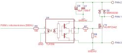
    Following your advice, I built a layout as below:

    Selecting Low RDS(on) Logic Level N-Mosfet for 3.3V Microcontroller & 12V Motor Control


    Connections:
    - 12V fan between FAN-1 and FAN-2,
    - 12V power supply for FAN-2,
    - mass for FAN-3.

    It worked for a few moments, then the C6 went up in smoke and the system stopped working, but I'm not sure it's the fault of this implementation. did i miss something? Thanks in advance...do
  • #25 17078856
    michalko12
    MCUs specialist
    Well, there are no miracles here. C6 released a magic balloon either due to overvoltage or reverse connection of C6 or supply voltage. The supply voltage may have increased if there is a diode at the output of the power source, because the arrangement of the elements fan, D2 and C6 created a boost converter circuit. There was no power supply. R8 is redundant.
  • #26 17078890
    robiw
    Level 26  
    As for C6, it's clear, it was probably too low voltage (16V), but why was the system damaged? By surges? After all, there is D2 parallel to the fan. What transil do you suggest (power supply max. 14V)? robin
  • #27 17078947
    michalko12
    MCUs specialist
    Was the fan power supply directly connected to the power supply, and e.g. the wires from the power supply to this system were thinner, longer? Diode D2 would do its job well if it was mounted close to the load.
  • #28 17078978
    robiw
    Level 26  
    The fan was connected to the FAN terminals and the power supply to them. The wires are about 20cm long, so it shouldn't matter...dow
  • #29 17079013
    michalko12
    MCUs specialist
    Somehow some of the energy from the fan preferred to be deposited on C6 and then U4 rather than completely deposited on D2. Something was wrong between the D2 cathode and the FAN2 terminal, maybe the terminal itself is of poor quality, or something was badly screwed/clamped. I can't think of anything else.
  • #30 17079078
    excray
    Level 41  
    C6 works as an energy store. When the key is turned on, a significant amount of current flows through it. Make sure that it is a low esr capacitor designed to work with high currents in the impulse.

Topic summary

The discussion revolves around selecting a low RDS(on) logic level N-MOSFET suitable for controlling a 12V motor with a 3.3V microcontroller, specifically for a PWM application with a load current of 10-15A. Participants suggest various MOSFET models, including PSMN2R7-30PL, IRLB8748PBF, and IRL7833PBF, emphasizing the importance of low RDS(on) values to minimize heat generation and the potential need for a heatsink. The necessity of using a gate driver to manage the MOSFET effectively at low gate voltages is highlighted, with recommendations for optoisolators like LTV817 and TLP250 for signal isolation. Concerns about switching losses and the impact of PWM frequency on performance are also discussed, with suggestions to consider driver ICs for better efficiency.
Summary generated by the language model.
ADVERTISEMENT