logo elektroda
logo elektroda
X
logo elektroda

Constructing a Half-Wave Dipole Antenna for Baofeng UV-82 Radio: Materials, Assembly & Tuning

mat134679 15189 11
ADVERTISEMENT
Treść została przetłumaczona polish » english Zobacz oryginalną wersję tematu
  • #1 17653385
    mat134679
    Level 2  
    Hello, I'm a beginner ham (you can call it that)
    I have a baofeng uv-82 radio and I would like to build a half-wave dipole for it, but I don't know how to go about it :-)
    1. I don't know what materials to use for construction
    2. In general, I do not know how to build a dipole (how to connect everything together so that it works as it should)
    3. How to choose arm lengths for the right frequency
    I am interested in listening on frequencies 136-174 (mainly around 148)
    Please help.
  • ADVERTISEMENT
  • Helpful post
    #3 17655603
    Sumar
    Level 16  
    Take this as a basis:
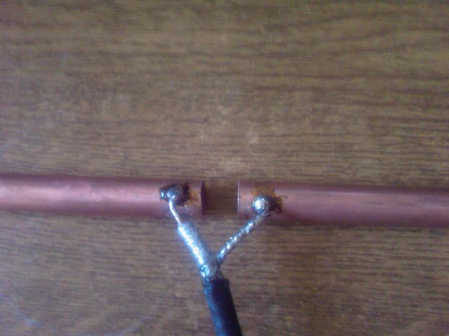
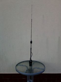
    Two copper pipes of 50 cm each, connected by an antenna cable soldered to the ends of the pipes.
    That is, simply two copper pipes, 50 cm long (75/148=50 formula) with a soldered antenna cable, running parallel to the pipes for a minimum length of 50 cm. And how you put it together mechanically to make it durable - let it remain your invention.
  • ADVERTISEMENT
  • #4 17655805
    mat134679
    Level 2  
    Thanks guys for your help. One more thing, what formula should I use to calculate the length of the tubes because on the forum I met with 3 formulas and each has a different value.
  • #5 17656322
    ElekTrick
    Level 20  
    mat134679 wrote:
    what formula should I use to calculate the length of the tubes because on the forum I met with 3 formulas and each has a different value.
    But what can be miscalculated here? Like a half-wave dipole, it's half a wave. The wavelength is 300/f[MHz]. And the dipole is made of 2 tubes, so each tube is 1/4 wave. And it needs to be shortened by about 5%.
  • ADVERTISEMENT
  • #6 17656513
    mat134679
    Level 2  
    ElekTrick wrote:
    mat134679 wrote:
    what formula should I use to calculate the length of the tubes because on the forum I met with 3 formulas and each has a different value.
    But what can be miscalculated here? Like a half-wave dipole, it's half a wave. The wavelength is 300/f[MHz]. And the dipole is made of 2 tubes, so each tube is 1/4 wave. And it needs to be shortened by about 5%.


    I mean that, like a colleague above, he gave me a link to the formula and there are two formulas for calculating the length of the antenna arms
    AND
    There is a pattern for this:

    L = 143/f

    f= the frequency at which you want to make the dipole.

    Then you divide the result by 2 and you get the length of one arm.

    So, at 172MHz it will be like this:

    L = 143 / 172
    L ~ 0.83
    0.83 / 2 = 41.5 cm - one shoulder

    II
    The basic formula for calculating a 1/2 wave dipole (2x ¼ wave) is:
    300 / f / 4 * k = radiator length in meters
    Where :
    300 - "speed" of light propagation (electromagnetic wave)
    f - is the frequency given in MHz
    4 - is ¼ wave
    k - shortening factor (different for each type of antenna)

    And so - for the PSP frequency in the country (average around 149MHz) [and not 172MHz], it is:
    300 / 149 / 4 * 0.96 = 0.483 m (48.3 cm) one leg of the dipole times 2 .

    And there the gentlemen argued which is good and I do not know how to calculate the length of the antennas for my frequency
  • Helpful post
    #7 17656575
    Sumar
    Level 16  
    Only II and for that we remove unnecessary additional division 300/4 and immediately accept

    L = 75 / f * k

    75 / 148 * 0.96
  • Helpful post
    #8 17656742
    _jta_
    Electronics specialist
    What is the impedance of the antenna input of this radio? Because if 300 ohms, it is appropriate to use a loop dipole.
  • Helpful post
    #9 17656760
    c2h5oh
    Moderator
    _jta_ wrote:
    What is the impedance of the antenna input of this radio? Because if 300 ohms, it is appropriate to use a loop dipole.

    mat134679 wrote:
    ...I have a baofeng uv-82 radio...

    Parameters of baofeng UV-82 available on Google without any problem.
    Typically these radios have an input impedance of 50Ω.
  • ADVERTISEMENT
  • Helpful post
    #10 17656876
    Radiokiller
    Level 30  
    Don't be surprised, Buddy, if your Baofeng refuses to work with an antenna other than your own.
    My UV 82 can "clog up" even with a 0 dB antenna.
  • Helpful post
    #11 17656980
    _jta_
    Electronics specialist
    I typed into Google "Antennas and antenna installations" - in the first place I got Janusz Bator's book for PLN 4.40 - in this book (not necessarily from Allegro, maybe it is in the library) there is a lot of information about antenna construction and their parameters. As far as I remember, an elementary half-wave dipole is about 150Ω and does not fit into the 50Ω input. But I may be remembering wrong because Ham radio course otherwise - see Antenna types and below Parameters and characteristics of the antennas.

Topic summary

The discussion revolves around constructing a half-wave dipole antenna for the Baofeng UV-82 radio. Key points include the materials needed, such as two copper pipes approximately 50 cm long, and the assembly process, which involves soldering an antenna cable parallel to the pipes. Various formulas for calculating the arm lengths based on desired frequencies (136-174 MHz, particularly around 148 MHz) are provided, including L = 143/f and L = 75/f * k, where k is a shortening factor. The input impedance of the Baofeng UV-82 is noted to be 50Ω, which is relevant for antenna compatibility. Users also discuss potential issues with the radio's performance with non-standard antennas and recommend resources for further reading on antenna construction.
Summary generated by the language model.
ADVERTISEMENT