Hi all,
I've been tasked with upgrading the basic electrical schematics of electrical cabinets we make to include the terminal connections ideally using free software if available.

I'm trying to use the free version of SkyCad Electrical, also tried the Design Spark Electrical from RS Component but this seems to be very time consuming to learn.., but to the main point, how do you guys draw terminal connections on the electrical schematics where you need to bridge terminals? How to represent this in the schematics? Can you point out some literature regarding this or link to the example how others are doing it, or maybe they are not?
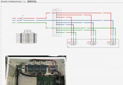
Below is the example of what I was trying to do, but I do not think that is the correct way as the schematic gets too complicated..
Any help will be greatly appreciated.

I've been tasked with upgrading the basic electrical schematics of electrical cabinets we make to include the terminal connections ideally using free software if available.

I'm trying to use the free version of SkyCad Electrical, also tried the Design Spark Electrical from RS Component but this seems to be very time consuming to learn.., but to the main point, how do you guys draw terminal connections on the electrical schematics where you need to bridge terminals? How to represent this in the schematics? Can you point out some literature regarding this or link to the example how others are doing it, or maybe they are not?
Below is the example of what I was trying to do, but I do not think that is the correct way as the schematic gets too complicated..
Any help will be greatly appreciated.


