logo elektroda
logo elektroda
X
logo elektroda

Calculating Capacitor Charges & Voltages: 300V System with C1=6F, C2=3µF, C3=4µF Connection

pakapi 53365 16
ADVERTISEMENT
Treść została przetłumaczona polish » english Zobacz oryginalną wersję tematu
  • #1 1981392
    pakapi
    Level 11  
    Phew and I can't do the task again. Here is the content:

    The three capacitors are connected as shown in the figure below. A voltage of 300v was applied to the resulting system. Calculate the value of the capacitor charges and the voltages on the capacitors, if the capacitance of the capacitors: C1 = 6F, C2 = 3 microF and C3 = 4microF.

    Calculating Capacitor Charges & Voltages: 300V System with C1=6F, C2=3µF, C3=4µF Connection

    I'm already doing 1 hour and it doesn't work. Pleats for help
  • ADVERTISEMENT
  • #2 1981729
    Maciej Zembaty
    Level 12  
    Q3 = C3 * Ext
    1 / C1 + 1 / C2 = 1 / C12 = C12
    U12 = U3
    Q12 = U12 * C12

    I guess it will be fine. Basic formula: Q = C * U
    In series connection of capacitors, the charges on the capacitors are equal.

    I hope its good. Good luck ;)


    Greetings
  • #3 1981742
    Różol84
    Level 11  
    C1 and C2 are connected in series, i.e. C12 = (C1 * C2) / (C1 + C2) then C12 is connected in parallel with C3, i.e. C123 = C12 + C3

    C = Q / U or Q = C123 * U

    Voltage at C3 = 300V
    voltage on C12 = 300V

    load on C3 ... Q3 = C3 * U
    charge on C12 ... Q12 = C12 * U

    voltage across capacitors C1 and C2:
    U = Q / C if C is small then U is large, if C is large then the voltage on it is small ...
    for our case, C1 is very large in relation to C2, therefore C1 will have a very low voltage and C1 will have a voltage close to 300V

    At least I think so..
  • ADVERTISEMENT
  • #5 1982102
    pakapi
    Level 11  
    Thanks boys. Then I'll edit the post and give you one more assignment which is totally nailed but what for you. :P Greetings

    Another, maybe simple, but for those who know what a steady state is:]

    The voltage source with electromotive force E = 150v and internal resistance Rw = 2 ohms, powers the circuit shown in the figure. Calculate the steady state voltage and charge across the capacitor. What is the value of the starting current of the source ?? Circuit data: R1 = 16 ohms,
    R2 = 8 ohms, R3 = 3 ohms, C = 0.5 microfs. F


    Calculating Capacitor Charges & Voltages: 300V System with C1=6F, C2=3µF, C3=4µF Connection

    And how can you explain to me nicely what this steady state is:].
  • #6 1985695
    jdjan1
    Level 26  
    Hello

    1) Put the drawing into the problem and we will try to solve it.
    2) Steady state is the state (in this case) after the capacitor is charged. The state from applying voltage to charging the capacitor is a transient state. Voltage and current follow an exponential curve.

    Best regards

    Jan
  • Helpful post
    #8 1986952
    Aleksander_01
    Level 43  
    Hello
    First, we calculate the initial source current, i.e. the moment at which the capacitor shorted. R2 and R3 connected in parallel = 2.18 ?.
    The resultant resistance of the entire circuit at the moment of switching on is Rz = Rw + R1 + R23 = 2 + 16 + 2.18 = 20.18?.
    Initial current = E / Rz = 150 / 20.18 = 7.43 A.

    In the steady state, the capacitor is an open circuit, i.e. the R of the circuit is = Rw + R1 + R3 = 2 + 16 + 3 = 21 ?.
    Circuit current = E / R = 150/21 = 7.14 A
    The voltage across the capacitor was set at the voltage level at R3, i.e.
    UR3 = I * R3 = 7.14 * 3 = 21.42 V.
    Q = C * U = 0.5uF * 21.42 = 10.71 uCulomba

    We have a steady state when all the currents and voltages in a given circuit have a steady value, i.e. despite the passage of time their value will not change.

    We have a transient state at the moment of switching on, switching off, connecting or disconnecting. State it lasts until all currents and voltages are stable.
    As a curiosity: the transient is still ongoing, but only from a mathematical point of view.
    greetings
  • #9 1999801
    pakapi
    Level 11  
    Okay, it's another game:]

    To the capacitor with a capacity of C1 = 20 micro F and the potential difference between the facings U = 100V, a second, same capacitor C2 is connected, uncharged. Calculate the amount of electricity stored in the condensates: a) before connection b) after connection

    Capacitor with a capacity of C1 = 4micro F charged to a voltage of U1 = 1200V connected to an uncharged capacitor with a capacity of C2 = microF. Calculate the voltage on the capacitors and the electric energy accumulated in the capacitors before and after their connection

    I have them for tomorrow, and I would like to ask if you could help me today
    In advance thx:]
  • Helpful post
    #10 2000020
    Aleksander_01
    Level 43  
    pakapi wrote:
    Okay, it's another game:]

    To the capacitor with a capacity of C1 = 20 micro F and the potential difference between the facings U = 100V, a second, same capacitor C2 is connected, uncharged. Calculate the amount of electricity stored in the condensates: a) before connection b) after connection

    Capacitor with a capacity of C1 = 4micro F charged to a voltage of U1 = 1200V connected to an uncharged capacitor with a capacity of C2 = microF. Calculate the voltage on the capacitors and the electric energy accumulated in the capacitors before and after their connection

    I have them for tomorrow, and I would like to ask if you could help me today
    In advance thx:]


    Hello
    The energy accumulated by C is expressed by the formula W = (CU ^ 2) / 2, the formula for capacity is C = Q / U. After attaching the second same C, the charge will not change and will be distributed exactly in half on each C. The voltage on each of C will also be half (50 V).
    Since the voltage decreased twice, the energy stored in C decreased four times.

    Follow the 4uF and 1200V energy formula.
    When you connect the second C with a capacity of 1 uF, the voltages on the capacitors will distribute inversely to their capacity, ie 4/5 of the voltage on the 1 uF capacitor and 1/5 of the primary voltage on the 4 uF capacitor.
    I will give you the results and you will try to calculate it yourself.
    1. for 4uF and 1200 VW = 2.88 J
    2. for 4uF and 240 VW = 0.115 J
    3. for 1uF and 960 VW = 0.46 J

    greetings
  • ADVERTISEMENT
  • #11 2000136
    pakapi
    Level 11  
    Okay, I just made a little mistake, but I think I'll be fine now. In the latter there is C2 = 6 micro F

    And I finally managed to do the first one myself, and instead I will give the last 3 tasks:]

    Croup1
    After charging the capacitors from the circuit shown below, the circuit breaker w was turned off. Calculate the values of: a) electric field energy stored in the charged capacitors, b) energy contained in the capacitor system after switching P from position 1 to position 2. Given systems: C1 = C2 = C3 = 20 micro F, U = 300V

    Calculating Capacitor Charges & Voltages: 300V System with C1=6F, C2=3µF, C3=4µF Connection

    Croup 2
    The voltage U = 10kV was applied to the flat air capacitor with the dimensions: facing surfaces S = 100cm2 and the distance between them d = 4mm. Then a glass plate with a thickness of 2 mm and the electric permeability of Er = 7 was inserted between the capacitor facings. Calculate the values of: a) the capacitance of the capacitor before and after inserting the glass plate, b) the intensity of the electric field in the air before and after inserting the glass plate, c) voltages on the individual layers of insulation

    Croup3
    Calculate the value of the voltage that should be applied to the AB terminals so that the Ucd voltage is equal to 6V.
    C1 = 2nF, C2 = 4nF, C3 = 6nF, C4 = nF.

    Calculating Capacitor Charges & Voltages: 300V System with C1=6F, C2=3µF, C3=4µF Connection
  • ADVERTISEMENT
  • Helpful post
    #12 2000316
    Aleksander_01
    Level 43  
    Hello
    Excercise 1.
    C1 and C3 connected in parallel is the resultant capacity C1C2 = 40 uF.
    There will be 100 V on C1 and C3, and 200 V on C2.
    W1 = W3 = (20 * 100 ^ 2) / 2 = 0.1 J
    W2 = (20 * 200 ^ 2) / 2 = 0.4 J
    the energy of the entire system will be 0.6 J

    After switching, C3 and C2 will discharge (I think so, but someone else confirm or deny it).
    Now I'm doing the third.
    Be right back.

    EXERCISE 2.
    First, I will give you the formulas
    C = ?S / d, E = U / d, E = Q / ?S, you can calculate these simple things yourself.
    After inserting the glass plate, two capacitors were formed in series. The sum of the voltages on these cond. Is equal to 10 kV. The charges are identical on these two capacitors.
    that is
    U1 = E1d1 and U2 = E2d2 d1 = d2
    U = U1 + U2 = E1d1 + E2d2
    because the loads are the same it
    Q1 = Q2 = E1?1S = E2?2S
    divide by S and get
    E1?1 = E2?2 or E1 / E2 = ?2 / ?1
    that is, the electric field intensity is inversely proportional to the relative permittivity (if you decrease the permeability, the electric field strength will increase).
    Now that's simple math, you'll be fine.
    greetings
  • #13 2000604
    pakapi
    Level 11  
    Seems good, but how did you find that the voltage will be distributed between C1 and C3 = 100V and C2 = 200v ?? And what does "^" mean ??
  • #14 2000703
    Aleksander_01
    Level 43  
    pakapi wrote:
    Seems good, but how did you find that the voltage will be distributed between C1 and C3 = 100V and C2 = 200v ?? And what does "^" mean ??


    It's simple. C1 and C3 are connected in parallel and C1C3 and C2 are connected in series. When connecting cond. In series, an identical charge will build up on all capacitors. The formula for the voltage across the capacitor is U = Q / C, so with the same charges and higher capacity, the voltage will be lower. If you have two capacitors connected in series with capacities, e.g. 100 nano and 300 nano and powered by 400 V, the voltage on them will be respectively: for 100 nano it will be 300 V and for 300 nano it will be 100 V. Take a pen, a piece of paper and check.
    greetings
  • #15 2000743
    pakapi
    Level 11  
    Okay, now I understand:] Thanks to everyone for your help and I hope that tomorrow I will get max from Kalsówki.

    ***********************
    dude just gave me a job I couldn't. Here they are: (Alexander, you did them but wrong. Should be 18v or -18v)

    Croup3
    Calculate the value of the voltage that should be applied to the AB terminals so that the Ucd voltage is equal to 6V.
    C1 = 2nF, C2 = 4nF, C3 = 6nF, C4 = nF.


    http://img54.imageshack.us/my.php?image=beztytuu3rm.jpg

    Who's gonna try to make them for me ??
  • #16 3533635
    zofja
    Level 1  
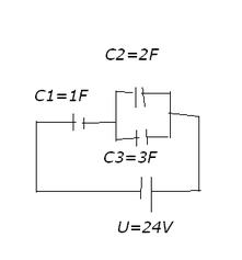
    would someone help me solve this problem?
    Calculate the charges and voltage on each capacitor if:
    Calculating Capacitor Charges & Voltages: 300V System with C1=6F, C2=3µF, C3=4µF Connection

    I personally worked
    Q1 = 20C
    Q2 = 8C
    Q3 = 12C

    U1 = 20V
    U2 = U3 = 4V
  • #17 3533939
    Malpa_gk
    Level 16  
    You did well :)

    [I am closing. June 22, 2008. Mariusz Ch.]

Topic summary

The discussion revolves around calculating the charges and voltages of three capacitors (C1 = 6F, C2 = 3µF, C3 = 4µF) connected in a 300V system. Participants explain the series and parallel connections of the capacitors, applying relevant formulas such as Q = C * U and the rules for voltage distribution in series and parallel configurations. Key points include that C1 and C2 are in series, resulting in a combined capacitance, which is then in parallel with C3. The voltage across C3 is noted to be 300V, while the voltage across C12 (C1 and C2) is derived from the charge and capacitance relationships. The conversation also touches on related capacitor problems and concepts like steady state and transient states in circuits.
Summary generated by the language model.
ADVERTISEMENT