logo elektroda
logo elektroda
X
logo elektroda

Calculating Capacitor Load: Using Capacity and Formula from Capacitor Layout Appendix

quaka456 14634 10
ADVERTISEMENT
Treść została przetłumaczona polish » english Zobacz oryginalną wersję tematu
  • #1 15386295
    quaka456
    Level 10  
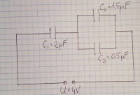
    Hello, how to calculate the load ( $$ Q_{2}$$ ) on a capacitor with a capacity $$C_{2}$$ ? (capacitor layout in the appendix)
    I am trying to use the formula here: $$Q=UC$$
    I substitute the data from the drawing for this formula.
    $$Q_{2}=4 \cdot 1,5=6$$ however, this is not a valid result.
    Thank you in advance for your help :)

     Calculating Capacitor Load: Using Capacity and Formula from Capacitor Layout Appendix1.jpg Download (185.1 kB)
  • ADVERTISEMENT
  • #2 15386320
    kryststgpom
    Level 25  
    You substituted the supply voltage, not the voltage, on C2.
    It should be Q2 = U2xC2.
    The formulas for parallel and series connection of capacitors can be used.
  • ADVERTISEMENT
  • Helpful post
    #3 15386331
    ryszard1955
    Level 20  
    Buddy, you are supposed to calculate the load in the C2 capacitor, and not in all three. In order to calculate the C2 charge, you need to find what will be the voltage on the C2 and C3 systems, the total capacity of which is their sum, i.e. 2 uF. As you can see, since C1 is also 2uF, the voltage across this circuit will be equal to half the voltage, i.e. 2V.
    So according to your formula, Q2 is going to be 2x1.5 = 3
  • ADVERTISEMENT
  • #4 15386361
    12pawel
    Level 34  
    After connecting C2 and C3, Ci are connected to the capacitors C1 (2uF) and C23 (2uF). The supply voltage is U = U1 + U23 and since they both have 2uF, the voltage is distributed in half, so 2V. So you have 2V on the replacement capacitor. You break the capacitor back into C2 and C3 and that they are in parallel, so the voltage is the same, i.e. 2V
    Such a trivial task. I advise you to go to a humanist because you will not be an engineer. Because if an engineer cannot, he knows where to look.
  • ADVERTISEMENT
  • #5 15386428
    quaka456
    Level 10  
    Thanks for the answers.
    I would like to make sure that I understand it correctly.
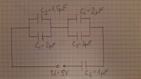
    If I have a layout like the picture and want to calculate $$Q_{4}$$ and $$U = 9V$$ this:
    $$U = U_{12} + U_{34} + U_{5}$$ that is $$U_{34} = 3V$$ and I'm using the formula now $$ Q = UC $$ that is $$ Q_{4}= 3 \cdot 2 = 6 $$ .
    Do I understand it correctly ?

     Calculating Capacitor Load: Using Capacity and Formula from Capacitor Layout Appendix1.jpg Download (313.54 kB)
  • #6 15386523
    12pawel
    Level 34  
    The C4 capacitor will be 1.57V so the charge is 1.57 * 2

    You cannot divide 9V evenly across 3 capacitors because they have different capacitance.
    You calculate the equivalent capacity of the entire system, then you calculate the total charge, and from the charge you calculate the individual voltages on the capacitors.
  • #7 15386614
    bodzio507
    Level 30  
    You have to define everything exactly, because everything can be calculated from the dependence Q = CU appropriately transformed.

    We do this type of task by folding the circuit into one capacitor and then returning it to the full circuit.
  • #8 15389688
    Artur k.
    VIP Meritorious for electroda.pl
    You have to remember the basic rules for connecting capacitors - in a parallel connection, we have the same voltages on each capacitor, the charges accumulated in them are different (according to the known formula). On the other hand, in a series connection it is the other way round - the charges accumulated in the capacitors are the same, but the voltages on the capacitors are different (of course also according to the known formula).

    Only this is needed to properly solve these tasks.
  • #9 15455611
    jesion40
    Level 27  
    ryszard1955 wrote:
    Buddy, you are supposed to calculate the load in the C2 capacitor, and not in all three. In order to calculate the C2 charge, you need to find what will be the voltage on the C2 and C3 systems, the total capacity of which is their sum, i.e. 2 uF. As you can see, since C1 is also 2uF, the voltage across this circuit will be equal to half the voltage, i.e. 2V.
    So according to your formula, Q2 is going to be 2x1.5 = 3
    This is probably the answer the test was about.

    However, in fact, without additional assumptions, it is impossible to answer this question. I do not mean the trivial assumption that capacitors do not have leakage. Much more questionable is the assumption that their charges were zero before they were connected and connected to this system.
  • #10 15456094
    Peter134
    Level 18  
    In such calculations, it is assumed that the system is perfect.
  • #11 15456934
    Artur k.
    VIP Meritorious for electroda.pl
    jesion40 wrote:
    Much more questionable is the assumption that their charges were zero before they were connected and connected to this system.

    And why is that?

Topic summary

The discussion revolves around calculating the load on a capacitor (C2) using its capacity and the associated voltage. Users clarify that the correct approach involves using the formula Q = U x C, where U is the voltage across the capacitor. It is emphasized that the voltage across capacitors in parallel remains the same, while in series, the charge is consistent. The total capacitance of connected capacitors must be considered to determine the voltage distribution. The conversation highlights the importance of understanding capacitor configurations and the assumptions made during calculations, such as neglecting leakage and initial charge states.
Summary generated by the language model.
ADVERTISEMENT