We know that the Buck circuit generally needs a "top tube" to control it, and this realization of raising its own voltage mainly depends on a capacitor, which is the bootstrap capacitor.
So how does this capacitor achieve its function?
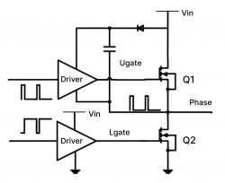
For example, a small capacitor is connected between the GS of the MOS. The MOS charges the capacitor when it is not turned on. When the MOS is turned on, when the S-pole voltage increases, the power supply voltage of the driver above will be automatically increased. At this time, the output voltage of the driver also increases and is connected to the G-pole of the top tube. In other words, the G-pole generates high voltage, and there is enough voltage difference Vgs between the G-pole and the S-pole, so the top tube MOS continues to be turned on.

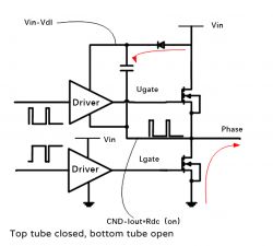
During the charging process, the IC will prohibit the upper and lower tubes from being turned on at the same time to prevent direct conduction. In other words, the upper tube will be turned off and the lower tube will be turned on, and then the diode D1 and the bootstrap capacitor C1 will form a charging circuit.

The input power passes through D1, C1, the lower tube, and finally to the ground (negative pole of the power supply), forming a loop to charge the capacitor so that the voltage on both sides of the capacitor is equal to the input power.
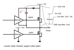
Conversely, when the lower tube is turned off, the previous loop is naturally cut off, and D1 is in reverse cutoff. At this time, the capacitor will keep the voltage change continuous, and the Vc voltage will gradually decrease with discharge without sudden changes.

However, during the charging process, since the capacitor has been charged, the Vc voltage is approximately Vin, so the Vgs of the upper tube is also equal to the input power supply, and this voltage is enough to turn on the upper tube.
In this way, a PWM cycle is completed, which is the charging and discharging process of the bootstrap capacitor.
So how does this capacitor achieve its function?
For example, a small capacitor is connected between the GS of the MOS. The MOS charges the capacitor when it is not turned on. When the MOS is turned on, when the S-pole voltage increases, the power supply voltage of the driver above will be automatically increased. At this time, the output voltage of the driver also increases and is connected to the G-pole of the top tube. In other words, the G-pole generates high voltage, and there is enough voltage difference Vgs between the G-pole and the S-pole, so the top tube MOS continues to be turned on.

During the charging process, the IC will prohibit the upper and lower tubes from being turned on at the same time to prevent direct conduction. In other words, the upper tube will be turned off and the lower tube will be turned on, and then the diode D1 and the bootstrap capacitor C1 will form a charging circuit.

The input power passes through D1, C1, the lower tube, and finally to the ground (negative pole of the power supply), forming a loop to charge the capacitor so that the voltage on both sides of the capacitor is equal to the input power.
Conversely, when the lower tube is turned off, the previous loop is naturally cut off, and D1 is in reverse cutoff. At this time, the capacitor will keep the voltage change continuous, and the Vc voltage will gradually decrease with discharge without sudden changes.

However, during the charging process, since the capacitor has been charged, the Vc voltage is approximately Vin, so the Vgs of the upper tube is also equal to the input power supply, and this voltage is enough to turn on the upper tube.
In this way, a PWM cycle is completed, which is the charging and discharging process of the bootstrap capacitor.


