logo elektroda
logo elektroda
X
logo elektroda

Rectified Voltage Value Dependence & Calculation: Tension after Rectification Explained

wojcik89 36377 19
ADVERTISEMENT
Treść została przetłumaczona polish » english Zobacz oryginalną wersję tematu
  • #1 3953868
    wojcik89
    Level 12  
    What does the value of the rectified voltage depend on and how to calculate it?
  • ADVERTISEMENT
  • #2 3953902
    majster_15
    Level 23  
    The rectified voltage is lower by about 0.7V because there is a voltage drop across the rectifier diode, and if we add a capacitor for filtration, the voltage will increase by √2.


    Regards, Matt.
  • #3 3953982
    wojcik89
    Level 12  
    So Wwy=(Wwe-0.7V)*sqrt(2) I understand well
  • #4 3954013
    cackoarek
    Level 26  
    You started to spill patterns and we don't even know what rectifier we are talking about.

    What if it was a two-wave rectifier in the form of a Greatz bridge? Or on thyristors...

    Added after 8 [minutes]:

    In general, the value of the rectified voltage depends on the type of rectifier (voltage drops on it), on the properties of the filter (if it is used) and on the load (which affects the efficiency of the filters).

    So it's actually quite a long topic.

    Added after 3 [minutes]:

    can the author elaborate his question for us?
  • #5 3954357
    wojcik89
    Level 12  
    We are talking about a power supply for an amplifier with a Greatz bridge 25A with 4 x 4700 uF filtering.
  • ADVERTISEMENT
  • #6 3954384
    majster_15
    Level 23  
    Well, in this case the output voltage will be lower by 1.2÷1.4V (drop on two diodes in the bridge) and will increase by √2, i.e. Uwy=(Uin-1.4)*√2 .

    Regards, Matt.
  • #7 3954501
    szod
    Level 33  
    :arrow: foreman_15 - Well, I don't agree. It counts a bit differently.
    Uout = ~Uin * √2 - 1.4V. It will work the way you described
    less voltage than it actually is.
  • #8 3955075
    cackoarek
    Level 26  
    Both :arrow: foreman_15 and :arrow: shod (although :arrow: shod is more right) they speak of a very unique situation.
    I agree that the voltage at the output of the rectifier can and will be of this value, but only if nothing is connected to the output - no load .

    From the fact that such we don't need the rectifier to work, but we do :arrow: wojcik89 explain that it is actually when his amplifier (apparently high power) is connected that the value of the rectified voltage (specifically its effective value ) will decrease. This is due to the so-called ripples - especially large under heavy load.
  • #9 3955098
    kortyleski
    Level 43  
    you are theoretically right... but:
    1) The amplifier provides a pulsed load, not a linear one, so between the individual pulses of a large load, the capacitors of the power supply have time to recharge to the peak voltage value ...
    2) The amplifier usually has a maximum operating voltage, if it is turned on and there is no signal, then this situation can be slightly
    treated as no-load operation, and we calculate the maximum voltage that can occur at the power supply terminals, reduced by a safe margin, so as not to damage the amplifier.
  • #10 4352344
    Radek18
    Level 15  
    Hello. I had the same problem. I was building a power supply for the amplifier and without the signal, the voltage was raised by the square root of 2. And after the signal was applied, it dropped by a few volts, which changed the impulse response of the amplifier to the given signal. I solved it by limiting the ripple voltage to about 1V with a current consumption of 15A. I used capacitors with a capacity of 130 mF and I will say that the ripple voltage was eliminated to the minimum possible.
  • #11 4352399
    adams987
    Level 35  
    Radek18 wrote:
    I solved it by limiting the ripple voltage to about 1V with a current consumption of 15A. I used capacitors with a capacity of 130 mF and I will say that the ripple voltage was eliminated to the minimum possible.

    Did you make a case for these capacitors??? Well, I guess with a voltage of 5V you got a ripple voltage of 1V, with a load of 15A.
  • ADVERTISEMENT
  • #12 4352472
    Radek18
    Level 15  
    I didn't make a suitcase but I have to admit that they take up a lot of space. I applied 6x22000 microfarads at 63V. The voltage on these capacitors is about 40 V. I use it to power the amplifier on several STK terminals.
  • ADVERTISEMENT
  • #14 6968450
    Anonymous
    Level 1  
  • #15 18185808
    kariak97
    Level 2  
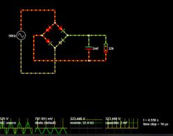
    Hello. Recently, I started designing a Graetz bridge power supply with an RC low-pass filter. This is what it looks like in the simulator:
    Rectified Voltage Value Dependence & Calculation: Tension after Rectification Explained
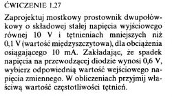
    I designed the whole thing so as to meet the conditions of task 1.27 from the Art of Electronics:
    Rectified Voltage Value Dependence & Calculation: Tension after Rectification Explained
    The only deviations from the command are the fact that the input is European standard current (230 V and 50 Hz) and zero DC component. Everything seems fine, but my energy balance is not right.
    One cycle of 230V rms AC generates the same power as 230V DC applied for one period. So I would expect that after rectification and filtering I will have about 228V at the output, but even from theory it follows that after rectification the voltage will be closer to the peak value, not the effective value. So the current at the output is able to generate more power than the one at the input, which is obviously wrong.
    In this case, the ripple is less than 0.1V.
    Attached is the .txt file for the simulator.
  • #16 18186104
    jony
    Electronics specialist
    But where is the energy/power balance wrong?
    Do you think tension is energy? And don't blame the capacitor for not knowing what rms value is, which was "invented" by man.
  • #17 18186150
    kariak97
    Level 2  
    The point is that 230V DC generates as much power as 325V AC at peak. If after rectification we have e.g. 322 V, then the heat generated on a given resistance will be greater than before rectification.
    edit
    So before rectification we have power P = 230^2/R, and after rectification P = 322^2/R, we just doubled the power of the current that comes out of the socket simply by rectifying it.
  • #18 18186203
    jony
    Electronics specialist
    kariak97 wrote:
    So before rectification we have power P = 230^2/R, and after rectification P = 322^2/R, we just doubled the power of the current that comes out of the socket simply by rectifying it.

    Have you calculated the current drawn from the socket?
  • #19 18186302
    kariak97
    Level 2  
    jony wrote:
    Have you calculated the current drawn from the socket?


    No, but I'm asking purely theoretically. I know it's calculated correctly, I just don't understand why the output is more powerful than the input.
    edit
    It seems logical to me (yes, I know that I think wrong, but I haven't found any information about it anywhere) that if the AC voltage at the input works (from the energy point of view) like 230V DC, then at the output of the rectifier with a filter it should be 230 - 1.2 V (drop on diodes).
    If anyone has any interesting link on this subject, I will gladly accept, now I don't even know what to type in google to find out.
  • #20 18186397
    jony
    Electronics specialist
    kariak97 wrote:
    I know it's calculated correctly, I just don't understand why the output is more powerful than the input.

    Because you didn't take into account the current drawn from the socket in the second case.
    And the resistance seen through the "socket" is different in the system with the rectifier + RC filter than if you connected the resistor R directly to the network.

    For example, a resistor with a resistance of R = 1kΩ should be connected to the "socket".
    The active power dissipated by our resistor is:
    P = 230²/1kΩ = 52.9W.

    And now we "deliver" a bridge + capacitor with a large capacity of 2mF in front of the resistor.
    And let the voltage behind the bridge be 320V.
    This time, the resistor will dissipate power equal to P = 320²/1kΩ = 102W (current I = 0.32A).

    Let's see what the current "drawn" from the socket looks like:

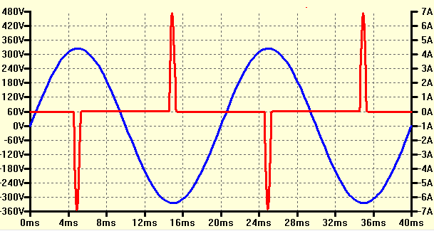
    Rectified Voltage Value Dependence & Calculation: Tension after Rectification Explained

    Where in blue you have the voltage in the network and in red the current "consumed" by our example rectifier.
    As you can see, the current is drawn impulsively and does not resemble a sinusoidal waveform at all (do you know why that is?).
    In addition, these pulses have a maximum value of 7A. And yet, only 0.32A flows through the resistor. Oh, a problem.

    As you can see, the matter is not as simple (obvious) as you thought at first.

    kariak97 wrote:
    It seems logical to me (yes, I know that I think wrong, but I haven't found any information about it anywhere) that if the AC voltage at the input works (from the energy point of view) like 230V DC, then at the output of the rectifier with a filter it should be 230 - 1.2 V (drop on diodes).

    I ask again. How is the poor capacitor supposed to "know" what RMS value is? And since the voltage in the socket actually has a value of 325V at peak.
    The capacitor will charge to the same voltage because this is the voltage in the socket.

Topic summary

The rectified voltage value depends on several factors including the type of rectifier used, the voltage drop across the diodes, the properties of any filtering capacitors, and the load connected to the circuit. For a Graetz bridge rectifier, the output voltage can be calculated using the formula Uout = Uin * √2 - Vdrop, where Vdrop accounts for the voltage drop across the diodes (approximately 1.2V to 1.4V for a full-wave rectifier). Under load conditions, the effective output voltage may decrease due to ripple effects, particularly in high-power applications like amplifiers. Capacitor selection and configuration are crucial for minimizing ripple voltage and ensuring stable performance.
Summary generated by the language model.
ADVERTISEMENT