logo elektroda
logo elektroda
X
logo elektroda

Minimizing Ripple in Full-Bridge Rectifier with RC Filter: Waveform, Polarity, Transformer Type

johnaweiss 507 6
ADVERTISEMENT
  • #1 21226464
    johnaweiss
    Level 2  
    In a full-bridge rectifier and RC filter, which combination of waveform, bi-polarity, and transformer-type will give the least ripple in the output (before a regulator)? Ie, how is ripple affected by:
    an AC source that goes negative on the troughs, vs a source that only goes positive, never below 0v?
    sine vs square source?
    pulse transformer vs non-pulse transformer?
  • ADVERTISEMENT
  • #2 21227015
    LEDówki
    Level 43  
    Try reading this article . The capacitor's purpose is to keep the current flowing when the voltage from the rectifier is missing. The larger the capacitance, the longer it sustains the voltage. However, a large capacitance needs to be charged with a high current so that the capacitor has time to charge to the highest possible voltage. With rectangular waveforms, the situation is similar, but there is a lot of interference.
  • ADVERTISEMENT
  • #3 21227495
    _jta_
    Electronics specialist
    johnaweiss wrote:
    an AC source that is only positive, never below 0 V?
    .
    This is an oxymoron - an internally contradictory term.
  • #4 21227681
    johnaweiss
    Level 2  
    >>21227495 I've heard different opinions on this. Some say a positive-only square wave is alternating current. But the definition of AC is not relevant to the question. I'm comparing an AC sine wave versus a positive-only square wave. I won't call it AC if you prefer.
  • ADVERTISEMENT
  • #5 21228066
    jarek_lnx
    Level 43  
    A difficult question, as the outcome depends on many factors.

    In theory: the ripple is higher the longer the time when the load current flows only from the capacitor.
    A rectangular waveform contains a section when the voltage does not change, which makes it easier to filter. The ripple can be smaller.

    In practice: a circuit with a mains transformer gives a few-odd volts of 100 Hz ripple easily removed with a linear stabiliser.

    A boost converter circuit gives tens - hundreds of millivolts of ripple, high frequency, very difficult to filter. A linear stabiliser will not help.

    Added after 3 [hours] 5 [minutes]: .

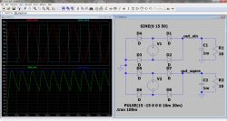
    Best viewed in simulation
    Screenshot of an electrical circuit simulation in LTspice XVII, showing graphs and a rectifier circuit schematic.
  • ADVERTISEMENT
  • #6 21228232
    _jta_
    Electronics specialist
    It would be good to specify what kind of waveform it is, because, for example, a rectangular waveform alternating after 10 ms U_0 and 0 will give much higher ripple than a 50 Hz sine wave with amplitude U_0 (and the same rms voltage) after rectification. In contrast, a rectangular waveform after 10 ms +U_0 and -U_0 after rectification will give no ripple (if this waveform and the rectifying diodes are ideal).
  • #7 21228268
    jarek_lnx
    Level 43  
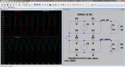
    @_jta_ Because after rectification we will get 100 Hz from a 50 Hz sine, and a unipolar rectangular waveform will not change shape.

    Rectifier circuit simulation in LTspice with sine and square waveforms.

Topic summary

The discussion centers on minimizing ripple in a full-bridge rectifier with an RC filter, focusing on the impact of waveform type, polarity, and transformer characteristics. Key points include that larger capacitance in the filter can sustain voltage longer, but requires high current for effective charging. Rectangular waveforms may produce less ripple due to their flat sections, while sine waves introduce a 100 Hz ripple post-rectification. A unipolar rectangular waveform can theoretically yield no ripple if ideal conditions are met. The choice between pulse and non-pulse transformers also influences ripple characteristics, with practical considerations highlighting the challenges of filtering high-frequency ripple from boost converters.
Summary generated by the language model.
ADVERTISEMENT