Control of WS2812 diodes via SPI with DMA - use of MOSI for timing generation
 .
.
A few years ago I presented a simple way to control an individually addressable LED strip based on bit-banging , i.e. the simplest operations on the IO pins of a microcontroller. Here I will show a completely different approach, which is based on using the MOSI pin from the hardware SPI port in combination with direct memory access (DMA). The WS2812 itself does not support the SPI protocol so this may seem strange, but I will explain everything in a moment.... the result is a WS2812 driver capable of sending large amounts of data to LEDs without blocking code execution by the microcontroller, i.e. also suitable for animation playback.
Basics of the WS2812 and the bit-bang method on the PIC18F45K50 .
I described the WS2812 communication protocol in the previous section. There I also showed the simplest implementation of it:
PIC18F45K50 as WS2812 LED strip driver (theory+library) .
This is where I assume familiarity with this topic.
I will pursue this topic on BK7231 .
Motivation to change control .
It would seem that nothing more is needed - bit bang is enough. But are we sure? We have to disable interrupts for the duration of the data transfer in this way, and we block code execution every time until the data transfer is complete. Nothing else can be done during this, otherwise we will mess up the timings. With long LED bars and animations this can take a really long time.
One would like to use interrupts, but the times required are really small:
 .
.
This might make you look for another way. However, there is another reason that practically forces this search.
I have attempted a method based on bit-banging on the BK7231. I experimentally determined how long one cycle of instructions lasts on this platform - one NOP - and selected their quantities so that I would have delays of, say, 0.4us and 0.8us.
Code: C / C++
I then typed in the code with preprocessor instructions creating a one or zero pulse:
Code: C / C++
I also optimised the pin setting and included it in the calculation, this I omit.
Finally, I tried sending pulses with them:
Code: C / C++
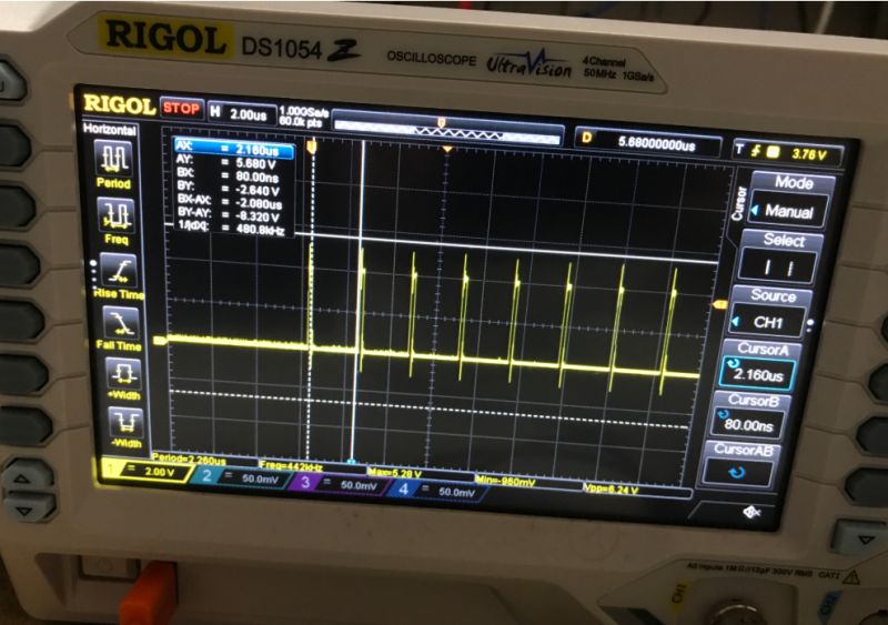
I fired it up, and:
 .
.
Everything looked fine, there are 8 pulses, but when I changed the number of commands "nop":
 .
.
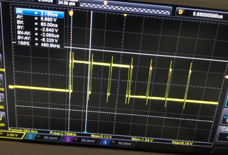
There was an unexpected, even (apparently) non-deterministic delay and only in part of the pulses? But why? After all, is it eight times WS2812_SEND_T0?
 .
.
I was a bit puzzled by this, but eventually I began to suspect that the problem was the cache and the way the instructions were being read from flash memory. Probably executing instructions from RAM (called "ramfunc") would also help, but there were difficulties with that too and we eventually decided on the method with SPI....
Basics of SPI DMA? .
Protocol SPI, to simplify, is based on two pins - clock (CLK) and data (MOSI - master out, slave in). Depending on the SPI mode, data is loaded by the receiver at a given clock edge. Based on 'pin waving', bit-bang, it looks roughly like this:
Code: C / C++
There's also the SS (Slave Select) pin, but I'm skipping that...
That's how you can send data from any digital outputs, but it's not efficient and again, it blocks code execution.
Many platforms offer more efficient solutions - hardware SPI and sometimes even with DMA (Direct Memory Access).
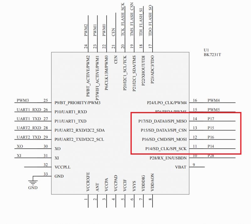
The platform used here, the BK7231, has one hardware SPI port:
 .
.
Using it, the display can be efficiently controlled, for example. But that leaves us with the DMA - what does it give us?
DMA, as the name suggests, provides the SPI hardware driver with direct access to memory. So essentially we have:
Code: C / C++
This piece of code will initiate the transfer of an array of bytes through the DMA at a given rate, and the transfer itself will not block the execution of the rest of the instruction, but will take place in the background, fully automatically.
The whole thing will no longer be affected by any interrupts or there instructions, the timings will be perfect....
Only what does this give us with respect to the WS2812, which expects control of a single pin? .
Using SPI DMA to control the WS2812 .
The whole trick is to use the independence of the SPI timing to simulate the signal required by the WS2812. Just how do you do this when they are two different protocols?
With SPI we have two signals:
- CLK/SCK, the clock, he can rather not how to carry data with him
- MOSI, data, their state (high or low) depends on what we want to send....
We can make a preliminary bet here that manipulation of the MOSI signal will allow us to generate the waveforms expected by the WS2812.
Now we just need to figure out how to manipulate this signal.
Let's recall the requirements:
 .
.
We want to be able to generate each of these signals. So I guess the finest unit of time it needs to have is 0.4us, then simply to generate 0.8us we would use it twice. Alternatively you could also try with 0.3us or similar.
What SPI transfer rate do we need to have to make one bit (from MOSI) last 0.3us?
1s/0.3us = 3,333,333
So let's take maybe 3,000,000, which is an SPI of 3MHz.
Then one bit takes about 1s/300000 = 0.333us
Two bits, on the other hand, will take about 0.666us . Apparently it's still within the margin of error, although I think I'll consider the option with three bits - 0.999us.
At this point we already know that we can generate T0H by sending one bit in the high state via SPI, and similarly, T0L will be two bits in the low state. So a total of 3 bits.
That is to say:
- time T0H is one bit lit in SPI
- time T0L is two bits off in the SPI
- time T1H is two bits lit in the SPI
- time T1L is one bit off in the SPI
That is:
- if you want to send bit 0 to the WS2812, you send T0H and T0L via SPI, i.e. 011
- to send bit 1 to the WS2812, we send T1H and T1L via SPI, that is 110
Rightly perfect, except that TH+TL must equal 1.25us, and 3*0.333us = 0.999us. It would be better to give 4*0.333us=1.332us, the error to 1.25us would be smaller. For this reason, we make a correction - we stretch one bit from the WS2812 to four bits from the SPI. .
Final:
- 0 for WS2812B is 0b1000 via SPI
- 1 for WS2812B is 0b1110 via SPI
It's just that the byte is 8 bits long, so it's easier to translate for us in binary:
- 0 0 for WS2812B is 0b1000 0b1000 via SPI
- 0 1 for WS2812B is 0b1000 0b1110 via SPI
- 1 0 for WS2812B is 0b1110 0b1000 via SPI
- 1 1 for WS2812B is 0b1110 0b1110 via SPI
A look up array can then be used:
Code: C / C++
The logical product with 0b11 is to put out bits other than the two least significant bits. This will ensure that the array index will be from 0 to 3 inclusive.
It is now left to break one byte for the WS2812 into four pairs of two bits each, and to write the finished bytes into the data array for the SPI:
Code: C / C++
And basically. that's it.
Now if we have some colour array to send to the WS2812, we simply "translate" it as shown into an array of bytes to be sent via SPI of an appropriately sized array (one byte for the WS2812 is 4 bytes on SPI) and then send the data so created via SPI DMA.
The rest of the code already depends on the platform we are using. .
The RESET condition for the W2812 could still be mentioned here, but sending the low state alone with the logic shown should no longer be a problem.
 .
.
Summary .
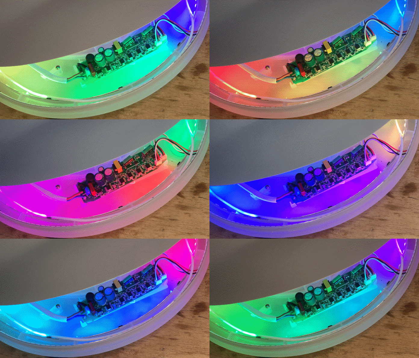
It would seem that the waveforms generated in this way will not be precise enough, but it seems that the WS2812 can tolerate them after all - I checked this in the topic about lamp from Action . You can safely play animations, indeed not only, because the once mentioned intelligent drawers also used this way. Such a bar can also be controlled via the DDP protocol.
Finally, if anyone wants to take a look at the source code, the project is open source . So far I'm happy with the implementation, so I'm unlikely to improve it, although there were a bit more complications with it, if only to increase the stability of the transfer we had to add a bit of zero bytes to the beginning and end, but that's rather due to the platform used already....
In any case - the animations work. And what are your experiences, have any of you tried writing your own WS2812 driver?


Comments
Here a simple example for the Arduino Nano: Link . There is no DMA, but here the author has decided to allocate as much as one SPI byte per ws2812 bit. This may come in handy when more precise timings... [Read more]
Interesting example, although on Atmeda rather this problem with the cache and bit-banging method does not occur? Additionally, it sends each byte separately. I'm still tempted to run these code executions... [Read more]
A nice coincidence as I am currently sitting on a clock on led ws2812:) . I can make the project available if anyone would like. I cut the aperture from milky plexiglass obtained from an old TV, the 7th... [Read more]
A familiar sight, I've been through this too, cool project. Self-built 7-segment colour display based on WS2812B . What are you going to drive it with? If you do, consider posting the whole thing... [Read more]
I too have started to build a clock but still lack the time. . PC [Read more]