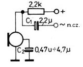
The use of a capacitor connected from the "Wy" foot to the ground in the case of 3-pin electret microphones results in an increase in gain and a higher level of the MW output signal. from the microphone.
Here you have
https://obrazki.elektroda.pl/75_1213721051.jpg is shown on the example of the internal scheme of these tonsilowskie electrets. By downloading the signal m.cz. from the "+" foot and by blocking the resistor in the source of the field effect transistor you have a typical amplifier circuit.
In general, the use of additional reinforcements on the external bipolar transistor added to such a microphone - when used as a CB microphone - is not serious. Then you hear on the radio full of "rectangular" modulations.
The MeO-55 electret microphone alone gives a much higher MV voltage. in a typical system - without blocking the "Wy" foot condenser ("+" foot directly to + 12V power supply, "I" signal output from the "100" output to the current signal line)
I made the renovation of the original pear from Alan 28, replacing the old dynamic transducer with this electret - of course, 10nF ceramic capacitors respectively + power supply 1kOhm + 47uF filter to ground and to the MeO-55 microphone in parallel 10nF to make the HF it did not follow the signal lines and nothing aroused.
You do not need any reinforcement.
For such a system, the MIC potentiometer Gain on the radio sets at most to 11 o'clock. Above this threshold you can already hear modulation limiter from the radio and flatten the modulation.
With such a system, the modulation is in a vein compared to the old dynamic insert.
There is no logical explanation for using here additional reinforcements that are in stupid fashion and then instead of the voice you hear one big gibberish and engine noise.
The constructors of these reinforcements would listen to earlier on the second radio before they put into practice. These rectangular, distorted modulations simply knock you to the ground.
In the case of a system with power supply through a resistor and collecting the signal from the transistor's resistor, the resistor is selected to half the voltage (more specifically, above the source potential) of the power supply (the highest signal dynamics, without unbalanced clipping of one of the signal halves) for a particular microphone.
For example, for MeO-55 with a white dot on the + 15V power supply, half of the voltage fell for resistors around 10-13k ohm (depending on the FET parameters).
Personally, however, I recommend the basic version without tapping the gain of the microphone itself.
In the case of typical modern small electret, double bed electrons, it is good to only add an emitter repeater (ie no voltage gain) so that the MIC Gain input potentiometer on the radio does not truncate its mains voltage. which will be placed on the resistor in the microphone transistor, from which we collect the signal. Then people reinforce them so that everything will be lost again on the divider, which will create a resistor in the collector along with the resistance of the potentiometer MIC Gain (usually 10 KOhm)


