logo elektroda
logo elektroda
X
logo elektroda

Deciphering and Understanding Car Wiring Diagrams: A Case Study on Lanos Schematic

jojo1231 51860 27
ADVERTISEMENT
Treść została przetłumaczona polish » english Zobacz oryginalną wersję tematu
  • #1 7843500
    jojo1231
    Level 9  
    I have a problem I need to learn how to read schematics and I can't quite figure out what is what and what for? Could someone help me to decipher the schematic this is an example schematic In Lanos: Deciphering and Understanding Car Wiring Diagrams: A Case Study on Lanos Schematic
  • ADVERTISEMENT
  • #2 7843516
    trans-serwis
    Level 39  
    A car electronics technician and a problem with the schematic? What is the problem?
  • ADVERTISEMENT
  • #3 7843671
    jojo1231
    Level 9  
    The problem is, for example, that I have a connector C210 I don't know what the bracket with 16. means, and next to it there is a given connector drawn, but I don't know which wire is from what?
  • #4 7844676
    pioart
    Level 38  
    16 is the pin number on the cube
  • ADVERTISEMENT
  • #5 7844770
    jojo1231
    Level 9  
    thanks a lot that's what I meant
  • #6 9468896
    mario205
    Level 18  
    Hi. If I may, I'll hook up with a similar problem regarding the symbols used in automotive wiring diagrams. There is no explanation in the diagram legend, so I will ask here. What does the rectangle with the number in the middle mean ?

    Deciphering and Understanding Car Wiring Diagrams: A Case Study on Lanos Schematic .
  • #7 9469382
    a.pacz
    Level 12  
    On the schematic, under the minus (ground) strip, a sequential numbering of circuits is carried out. The number in the rectangle indicates from which place on the schematic the circuit comes, or where the continuation of this circuit is. The example part of the schematic is too small and you can't see the lower strip with the minus connections (terminals 31) under which is the circuit numbering.
    If there is still something unclear, I will add it.
  • #8 9469416
    mario205
    Level 18  
    here you go, the whole excerpt

    Deciphering and Understanding Car Wiring Diagrams: A Case Study on Lanos Schematic
  • #9 9469600
    a.pacz
    Level 12  
    On this excerpt are shown circuits from No.29 to No.42. To locate circuits 17 and 19 (numbers in rectangles) you need to look for them on the previous parts of the diagram. Is everything clear now.
  • #10 9469700
    mario205
    Level 18  
    Yeah, right. That 17 is the mass point. Thanks for the clarification.
  • #11 9469750
    trans-serwis
    Level 39  
    You have misunderstood. 17 is not a mass point.
  • #12 9470019
    a.pacz
    Level 12  
    !7 is the no. of the circuit that is described under the minus line. In the circuit above 17 there will be a rectangle with No. 29, and in the circuit above 19 there will be a rectangle with No. 33.
    Write down if you found these circuits. A circuit in this sense is the vertical connections over the numbers under the minus line.
  • #13 9470073
    Zico63
    Level 37  
    Simply put, in other words, on the excerpt from the schematics containing the number 17 under the dash, look for further string the red-white wire of 1.0mm² (RO-WS 1.0) with square 29, which is written about by Colleague A.pacz .
  • #14 9472952
    mario205
    Level 18  
    Thanks. I already caught what's going on with the rectangles. I have one more dilemma because I don't quite get it. How to interpret the perimeter, since there are the empty ends themselves ( I think that's how the female end is marked but I'm not sure )? What in turn is meant by that 12 in the black rectangle and pins 1,5,7,8 and 9 ? Judging from the schematic as a whole, pin 1 should be connected at startup to line 31, as long as the bendix and starter relay solenoid are powered from this line and further up to the starter, what about the others ? Is this perhaps how the connection to the ignition switch is marked ?

    Deciphering and Understanding Car Wiring Diagrams: A Case Study on Lanos Schematic .
  • #15 9473006
    carrot
    Moderator of Cars
    This is the box for the relay in the box, not used for anything in this model (nevertheless, the boxes are the same in all models and there are leads made for it)
  • #16 9473266
    Zico63
    Level 37  
    Under the large gray box, that is the image of the fuse box - there are markings, for example. G2/5 , G2/6 , U1/8 , etc. According to this:
    http://www.a2resource.com/electrical/CE2.html
    page, you find a colleague the corresponding prongs and in them the pins. And so, for example: symbol G2/6 is a white plug G2 , pin 6 that is the third from the top right in the plug. If a "wire" is not routed from a given point - it is not accretively used.
    The markings on the relay box itself correspond to the markings on the box ( 1, 2 itd.). - rather than the relay itself; these are, for example, 30, 87 , etc.
    Further: the lines at the top of the "box" are permanent internal connections, the so-called line. And so, 30 is a fixed plus; 15 plus from the ignition (with ignition, ignition - they say differently); X this line under current at the time of what 15 but goes out when the starter is turned (plugged in large consumers, going out at start-up - relieve the battery); well and 31 - fixed ground. There are still left lines marked with lowercase letters of the alphabet: a, b, j or others: these are other internal connections pulled to the next page of the book.

    Incidentally: 12 in Golfs is always used, even in D versions or choppers there is a plug relay. Probably, dealing with the alarm, they did not include it in the drawing; it did not belong in the case :wink: .
  • #17 9474262
    mario205
    Level 18  
    And all is clear :D . I compared with the general schematic and indeed the glow plug relay is embedded in this location, which is marked #53. Thank you colleagues for clarifying the subject.
  • #18 10600908
    utut92
    Level 11  
    If anyone has come across this topic surely he is tired of something or does not know something. I recommend the book titled: "Reading electrical schematics" Stanislaw mikołaj Słupski, I recommend the whole book but from page 33 we have instructions on how to read vaga schematics. pzdr
  • #19 17119453
    kuhnro2
    Level 14  
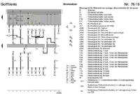
    Can someone suggest what the author meant by N1 (in a circle) and B9 (in a circle)?
    Deciphering and Understanding Car Wiring Diagrams: A Case Study on Lanos Schematic

    E4 is the long light switch in the steering wheel. Why does the low beam line go there?
  • #20 17119504
    tzok
    Moderator of Cars
    N1 and B9 are the branch points of the wires.

    There is no legend to the diagram and this is just a fragment of the diagram. Turning on the high beam turns off the low beam.
  • #21 17119514
    kuhnro2
    Level 14  
    tzok wrote:
    Turning on the high beam turns off the low beam.


    Are you sure? After all, jumper B9 connects J2 and J3.

    To my knowledge in Passat B4 - high beam turn on as additional bulbs.
  • #22 17119570
    tzok
    Moderator of Cars
    What is J2? It goes somewhere else... High beam is 56a, low beam is 56b, 58 is parking lamps.

    I can't read the function of switch E4 from this diagram. The legend and the rest of the schematic are missing. What car does this part of the schematic apply to? VW is not my hobby ;) turning off the dipped headlights depends on the version of the lamps, when they are on dual filament bulbs (e.g. H4) they are turned off, when they are on separate bulbs, they usually light simultaneously.
  • ADVERTISEMENT
  • #23 17120036
    kuhnro2
    Level 14  
    tzok wrote:
    What is J2? It goes somewhere further... High beam is 56a, low beam is 56b, 58 is the parking lamps.

    I can't read the function of the E4 switch from this schematic. The legend and the rest of the schematic are missing. What car does this part of the schematic apply to? VW is not my hobby ;) the switching off of the dipped headlights depends on the version of the lamps, when they are on dual filament bulbs (e.g. H4) they are switched off, when they are on separate bulbs, they usually light simultaneously.


    I feel that these questions must be answered by VW specialists.
    For my questions, nothing more is needed to answer them.
    Your two questions are answered earlier.
  • #24 17120451
    tzok
    Moderator of Cars
    In my opinion, this is a light horn, that is, in one position you flash the long and the low beam (even if they were not on), and in the opposite position you turn on only the long (the low beam shines "through" the light switch, which is not in this diagram).
  • #25 17120683
    kuhnro2
    Level 14  
    tzok wrote:
    In my opinion, this is a light horn, i.e. in one position you flash the long and the low beam (even if they were not on), and in the opposite position you turn on only the long (the low beam shines "through" the light switch, which is not in this diagram).


    Thin lines in the schematic are explained as "internal connections" i.e. connections inside (usually in the fuse box).

    The voltage to the low beam goes from the light switch- internal line h (I know this from another part of the schematic - not connected here), comes out with connector J2 (this is already visible on the schematic attached here), goes to point B9, then there is again an "internal connection" that leads to connector J3, further it flies to fuses S1, S2 and to the bulbs.

    I don't know why on this diagram flies from point B9 voltage to the high beam switch (E4), and I asked about this.

    After all, to this E4 flies the battery voltage (30) and this is switched on the high beam.

    From practice, however, I know that when my low beam switch failed (the one that provides voltage on the h line), then with the handle (that is, here E4) it was not possible to permanently switch on the high beam. They lit only as long as I pulled the handle towards me - when I let go - they went out.
    So the connection from B9 to E4 - it matters :) .
  • #26 17120813
    hobbista
    Level 22  
    Diagram our for separate bulbs for low and long. With the light switch you turn on the low beam - jumper B9 to J/3. Turning on the long - E4 short circuits 56 with 56a. Both bulbs are lit. So-called click regardless of the position of the light switch - connects 30 with 56a.
    However, if there were headlights for one H4 bulb, the scheme would be a little different. There would be no B9 jumper and there would be a J/3 connection to E4 T5b/2.
  • #27 17121660
    kuhnro2
    Level 14  
    hobbista wrote:
    Long-range switch - E4 short circuits 56 with 56a. Both bulbs are lit.
    That is, in this situation, the light switch is loaded with 4 bulbs?
    I mean 220W (4 x 55W). I thought that the high beam bulbs are then powered from 30 (battery +).
    In that case, the 1.5mm2 wire is a bit on the contact.
    Isn't it worth giving a relay reliever for high beam and low beam behind the E4 switch (one light switch has already died for me)?

    hobbista wrote:

    The so called click regardless of the position of the light switch - connects 30 to 56a.

    Is this the mode as you momentarily pull the handle towards you?
  • #28 17121730
    tzok
    Moderator of Cars
    All in all, I hadn't thought of that.... this switch in one position feeds the long from the low beam circuit (and this is the stable position), and in the other position it feeds the long directly from the battery (and this is the momentary position). Connection 56 (T5b/3) is therefore the input (not the output) of power from the low beam.

Topic summary

The discussion revolves around understanding automotive wiring diagrams, specifically focusing on the Lanos schematic. Users express difficulties in interpreting various components, such as connectors and circuit numbers. Key points include the identification of pin numbers on connectors, the significance of rectangles with numbers indicating circuit origins, and the interpretation of relay and fuse box markings. Participants clarify that certain symbols represent internal connections and branch points, while others discuss the implications of specific wiring configurations, such as the relationship between low and high beam circuits. Recommendations for further reading on electrical schematics are also provided.
Summary generated by the language model.
ADVERTISEMENT